[Alisha] Status Update 11.16.19
[Problem-Solving]
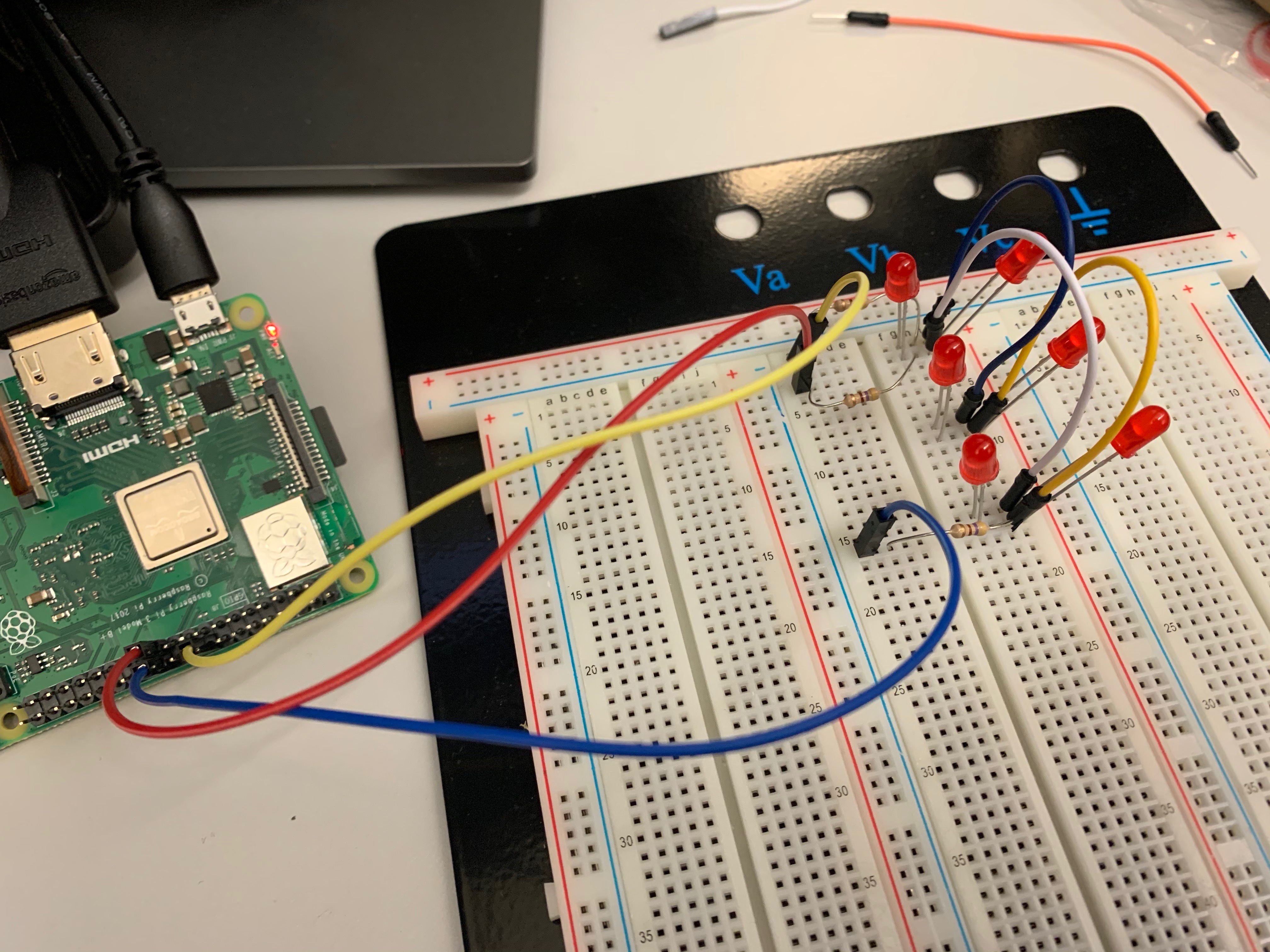
We had two primary problems to solve this week: (1) come up with a cleaner composition for connecting all our components together and (2) successfully incorporate the LEDs into our scheme (something we’d overlooked).
Accessing the pins with the PiCap in place was cumbersome and offered limited access to the full range of RPi pins. We originally wanted to use a pin header between the RPi and PiCap; the intermediate pins we needed to access would be bent out at 90º and soldered to wires. This wasn’t practical and prone to breakage, so we’ve instead used shorter jumper cables to make the assembly more compact.
Until this week, we hadn’t realized there was a seemingly inescapable lack of available GPIO pins to drive our red/green LEDs, meant to be visual seat availability indicators. After a deep dive into the PiCap schematic, the documentation for the MPR121 chip, and the code library specifically designed for that IC, I was able to reclaim another 4 GPIO pins that weren’t driving relevant parts of the PiCap. These 4 pins, paired with a multiplexing technique I used called “Charlieplexing,” will let us drive our red/green LEDs.
[System]
- Choosing and standardizing a scheme for the packet data that we send
- Testing data aggregating on the server side to make sure requests were queuing correctly
- Solving our GPIO pin access problem
- In turn, solving our LED problem
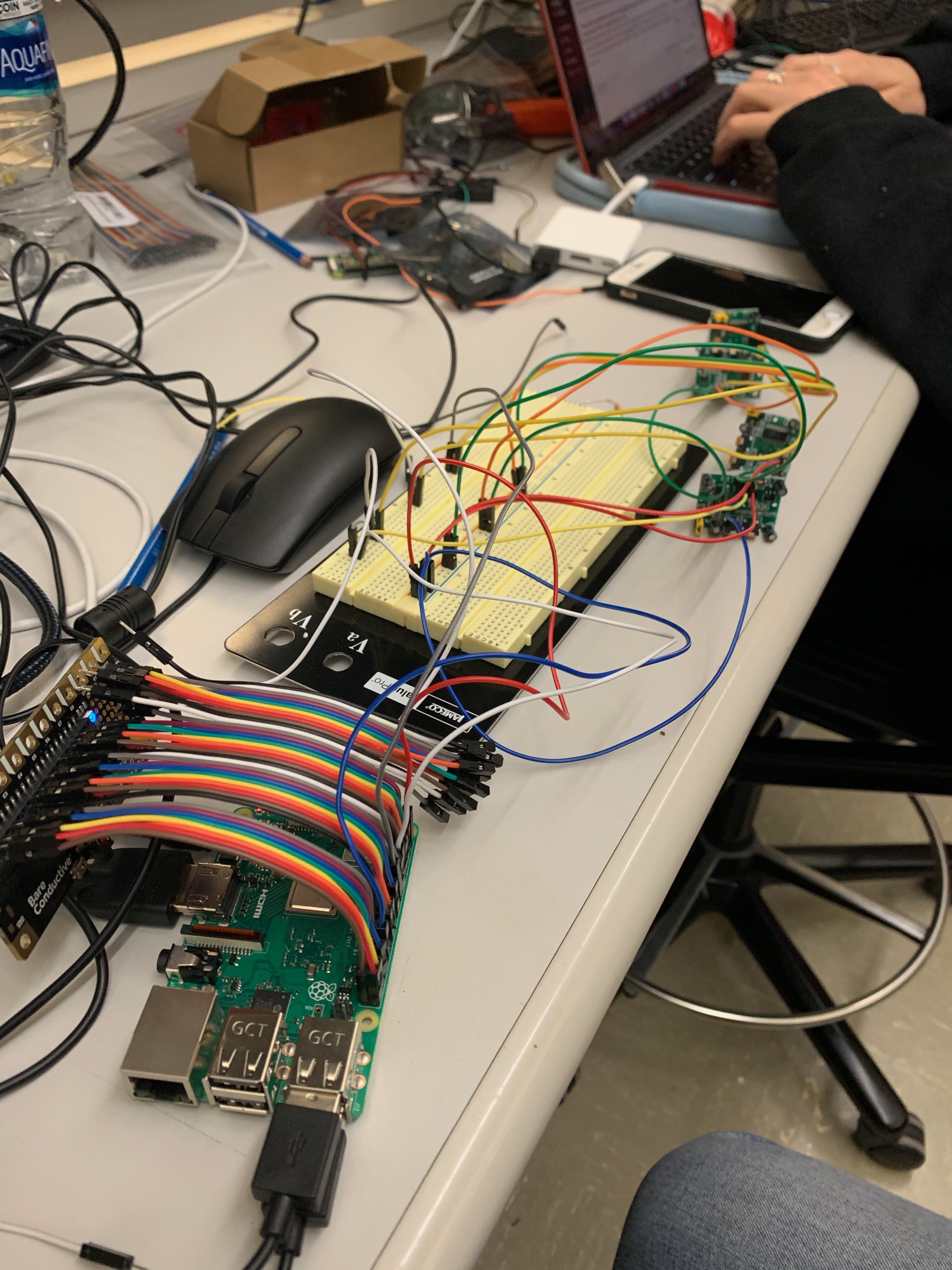
- Wiring several sensors and a pi cap to separate RPis and debugging communication
We now have a fully connected system with hubs that individually update the server!
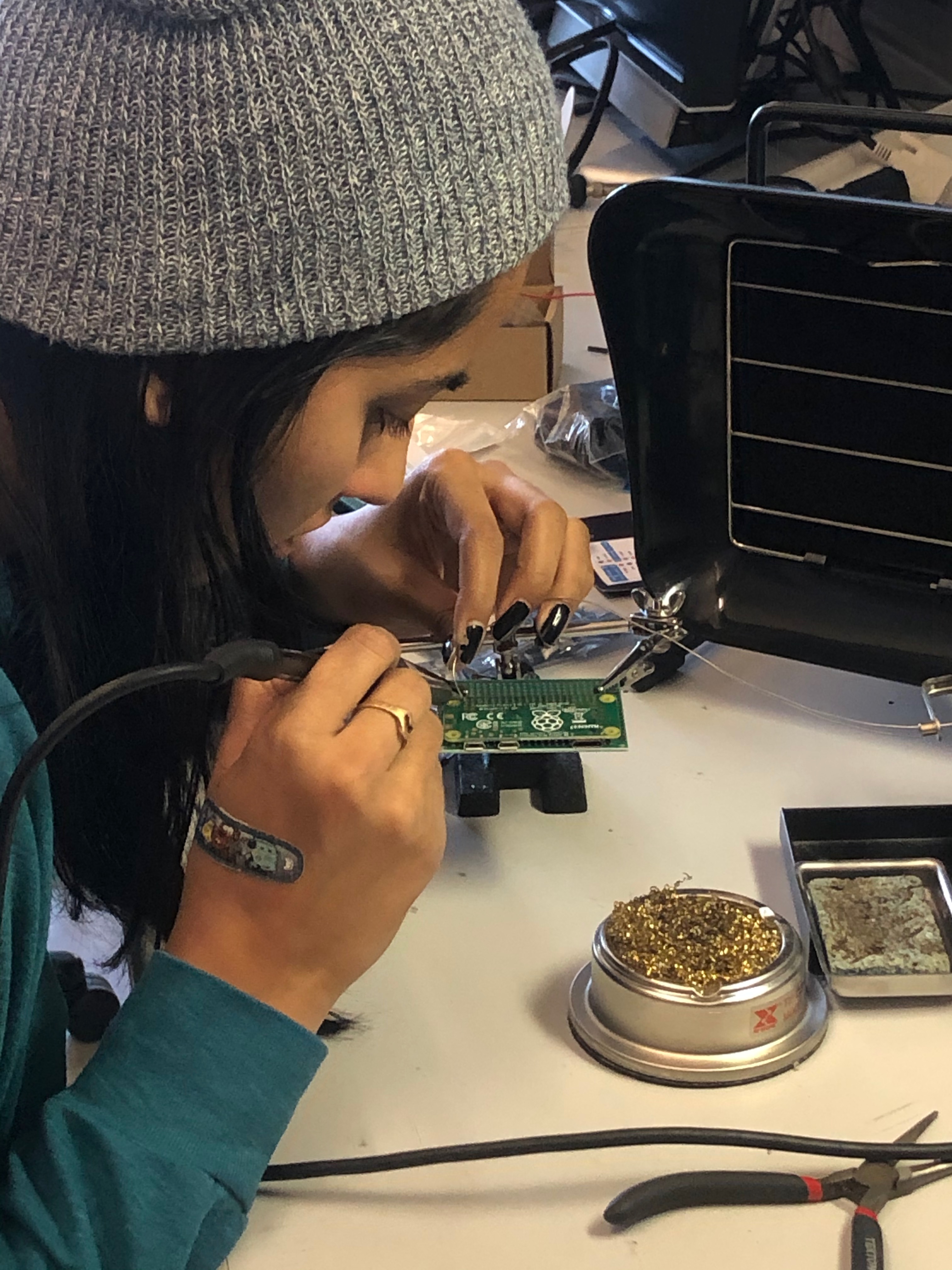
We also purchased RPi Zero W’s as a cheaper and smaller alternative to the RPi 3B+’s we were using earlier. I spent some time this weekend soldering on the headers to those Zero boards. We do still need to debug some connectivity issues, and demoing with the 3B+’s is our backup plan.
[Demo]
We’ve finalized what our demo setup will look like: foamboard carrel top with a 3/4″-ply base as the desktop, all sitting on a table. The foamboard carrel is built but we still need to source a table. On the system side, we’ll have two RPis, each representing a set of 7 carrels. We need to order a few more sensors and wires to bring together our final demo setup and max out all of the ports on each hub. All of our primary parts arrived already, so we’re pretty solid.
Deliverables for next week:
- Test that we’re meeting our timing requirements for response times
- Source a demo table and test system while fully mounted
- Print new casings for our sensor hubs with updated dimensions
- Print the cylinder caps for the PIR sensors