09/28/2019 Team Update
Jake Zimmer Status Update
What did you personally accomplish this week on the project? Give files or photos that demonstrate your progress. Prove to the reader that you put sufficient effort into the project over the course of the week (12+ hours).
This week, I figured out how the galvanometers actually worked and traced the sample driver PCBs to get a better idea of how they are currently implemented. These changes are being reflected in the schematic design.
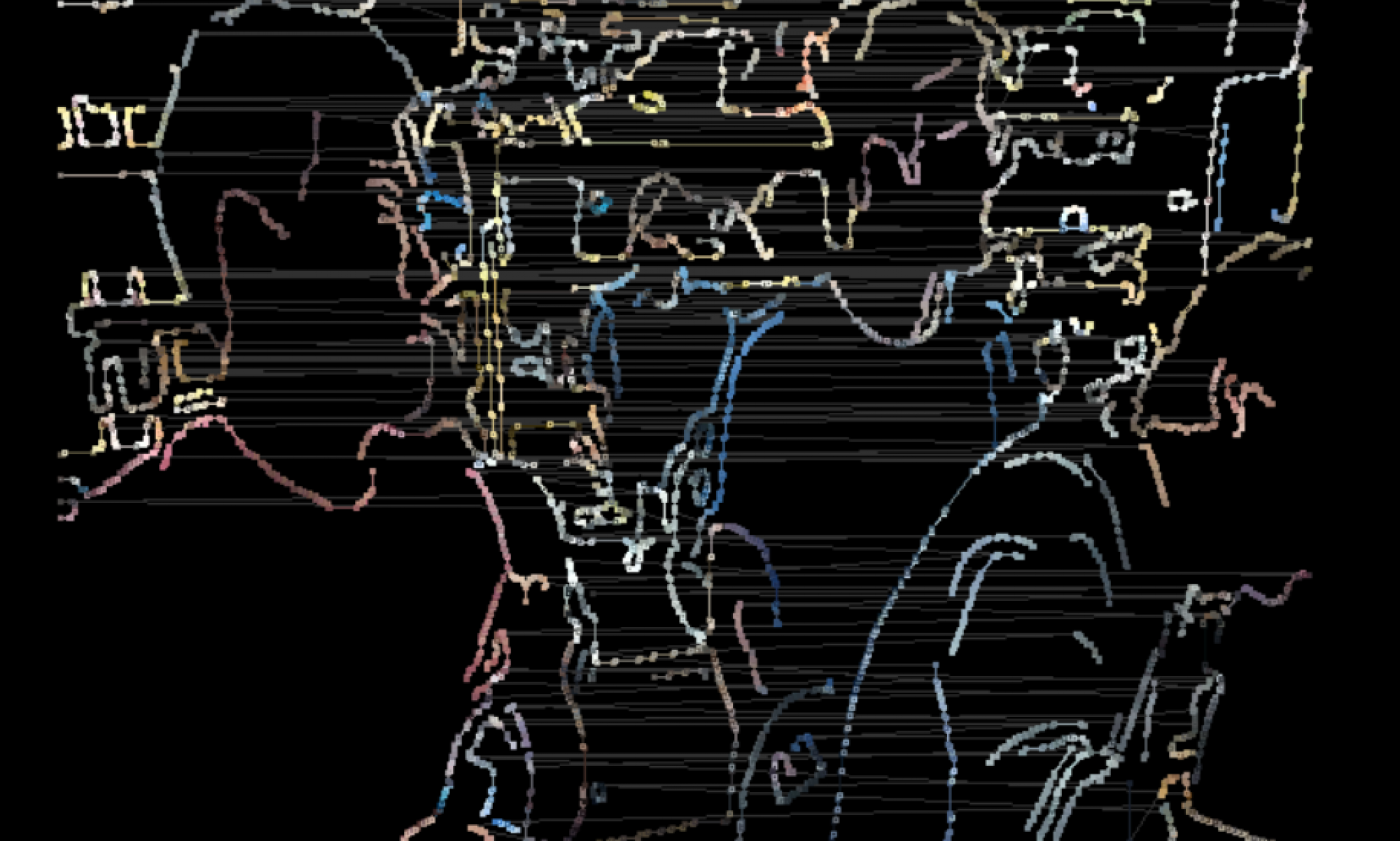
This is a composite image that helped me trace connections in the Chinese driver boards. It is composed of processed photos of the top and bottom layers of the boards.
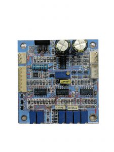
Additionally, this is the progress that I have made so far on the schematic design : laser
And here is an image of the board layout that I have done so far. This is a rough layout of components because the schematic design is still in flux and so making a pretty layout is lower priority.
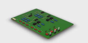
Note: not all 3D models are created. The blue shapes are large capacitors and the red shapes are potentiometers of various sizes.
Is your progress on schedule or behind? If you are behind, what actions will be
taken to catch up to the project schedule?
It is a little behind schedule because we had to wait until we had the galvanometers before making significant progress on the schematic. We expected to be able to find more information about the galvos online.
What deliverables do you hope to complete in the next week?
Next week I hope to make a DAC test board and order the parts for the PID subsystem so that I can begin experimenting with the PID portion of the project before manufacturing.
Enes Palaz Status Update
Focus of my work was ordering DAC that we selected as a team and read through its datasheet in detail to make preparations for the interface that I am going to code for it in the upcoming week.
I read through the specifications on how to communicate with the DAC using SPI protocol and listed steps needed to successfully configure it. In addition to this, I noted the timing constraints for the DAC trigger so I can take those into account during the development phase.
I also worked on some research on SPI libraries that are available to use in multiple languages while we try to decide in choosing C or Python as our main language in the project based on performance constraints. As a result of the research, I decided to use WiringPi GPIO library because of its speed thanks to it being written in C. We want to utilize the performance advantage that comes with this.
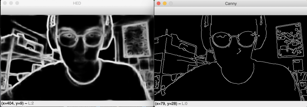
Lastly, I made some research on other edge-detection algorithms that are based on deep-learning models that could improve our performance. I am mainly evaluating performance of HED(Hollistic Edge Detection) and Canny Edge Detection which is the method that we are currently using.
My progress is still on track since I am on hold for our DACs and breakout boards for these DACs to arrive. Therefore, I didn’t need to move anything in the schedule.
Hopefully, our parts are going to arrive on Monday (09/30/2019) so I can start reflowing those on breakout boards and start configuring. I am planning to be done with successfully outputting desired values on all 8 channels of the DAC trigger all of these in synch. The verification of this is going to be done by using a multi channel oscilloscope.
Eliana Cohen Status Update
- What did you personally accomplish this week on the project?
- Integrated earlier OpenCV livestream output with ILDA conversion on our test raspi, and tested the time to convert a frame to ILDA.
This included making the initial test python code into modular libraries, and redefining the software stack structure for the project. An example of a frame converted in real time can be seen below:

-
- Wrote pseudo-code for thread-safe double-buffer interface between video livestream and DAC interface.
- Code is mostly finished, just requires a test-bench to benchmark its speed and thread safety. High-level structure of the double-buffer is below:
- Wrote pseudo-code for thread-safe double-buffer interface between video livestream and DAC interface.

-
- Assisted in some schematic review for PID design.
- Is your progress on schedule or behind? If you are behind, what actions will be taken to catch up to the project schedule?
Mostly on schedule, after I integrated the video feed with the ILDA conversion python library, I found the python library was too slow (0.7 second frame conversion time) to keep up with our 10fps requirement. Hence, I will write up a C-version of this module by the end of this weekend, and so I will still finish this module-integration on time.
- What deliverables do you hope to complete in the next week?
By next week, I should have completed:
- Ensuring live-generated ILDA frames work on our hardware system.
- C-Version of the ILDA conversion library fully tested and completed.
- Double-buffer library fully tested and completed.
Team Status Update
- What are the most significant risks that could jeopardize the success of the project? How are these risks being managed? What contingency plans are ready?
The PID controller is a big point of uncertainty for this project for two reasons. The first is that the PID controller is done in analog circuitry which means it is a bit difficult to make conceptual changes on the fly. Some laser systems seem to implement a PIDD controller with different D terms for high frequency and low frequency changes. To mitigate this risk, we will protoboard the system before getting manufactured boards. The second risk is that the feedback system for the PID controller is somewhat unusually constructed. The galvanometers use an LED and two photocells with a blocking element to derive a positional component. To mitigate this risk, we will scope the outputs of this element thoroughly to derive a good method of receiving feedback from it.
Computation time from video frame to DAC output is another concern. Preliminary testing revealed that trying to package the contour bytes from OpenCV to ILDA format in python were too slow (~0.7 seconds per frame), so we are switching to using C for this conversion for speed improvements. This should hopefully improve our speed limitations, but more testing is required.
In order to increase our performance more in case that we didn’t reach high enough frame rates in our C implementation, we added smoothing and filtering work in our schedule to develop a fast filtering step between contour detection and ILDA conversion to reduce the number of points converted. This method will mainly detect really small and unrelated contours that is not worth drawing so we can reduce the workload while not losing any visual context.
- Were any changes made to the existing design of the system (requirements, block diagram, system spec, etc)? Why was this change necessary, what costs does the change incur, and how will these costs be mitigated going forward?
We changed our software stack structure after realizing Python was too slow
(for our 10/fps requirement) to handle contour to ILDA conversion.
The new software diagram is below:
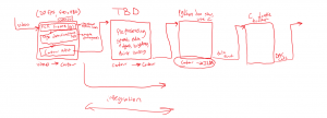
We refined some of the requirements:
The laser shall draw frames at 10 frames per second because it is proximal to the classic animation framerate of 12 frames per second (which is proven to look visually fluid) while also being an easy divider of 30 frames per second, the modern framerate.

A frame shall consist of a number of points less than 12,000 (12kpps) divided by the framerate.

The laser shall achieve 90% accuracy on the 12kpps ILDA test pattern by visually conforming to 9 out of 10 of the features highlighted in the pattern specifications.
- Provide an updated schedule if changes have occurred.
These are the changes to the current schedule: 09282019_sched
What is LaSEEr
LaSEEr is a system that converts the real world to lasers. LaSEEr uses a camera or video feed and converts that stream into a laser show. We are going to build a project that consists of a camera, small computer, lasers, and laser beam guidance mechanism. We will achieve a laser traced style animation with this system of >10 frames per second. This project will hopefully result in a cool way of visualizing the world around us in a very unique way.
The image from the camera is traced and the edges and colors of shapes are converted to movements and red-green-blue power outputs for the lasers. Instead of physically moving the lasers themselves, we are using mirrors to guide the light of the lasers. By combining red, green, and blue lasers and then modulating their power, we can make a singular beam of any color.
For more information, please refer to the proposal presentation: 18500_A2_Proposal_Presentation