
Bill:
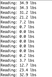
The first HX711 amplifier was not giving me any readings, and I think it might have gotten damaged from the several soldering and desoldering attempts. I decided to just try again with the second amplifier. I soldered a 5×1 female header pin to the amplifier, as well as the leads from the load cell, and connected the amplifier to the Arduino to try and see if I could get reading with the second amplifier. I used the HX711 interface that was provided by Sparkfun, and wrote code that just constantly read from the amplifier in an infinite loop. I managed to get readings from the amplifier, but for some reason, I was getting negative readings despite the fact that everything was connected correctly. After reading up a bit online, it turns out that in the case of the readings being negative, I can just switch the positive and negative outputs of the load cell. I had to desolder and resolder the leads, and that fixed the issue with the signs. I tested the load cell by just gently pressing on it with my fingers.
The readings look like this. The calibration of the load cell is off because I just picked a random value for the calibration. This is not important in our case, as we do not care about the actual weight of the glass. We just need to detect whether there is a glass or not. The next step would be to build an actual platform with the load cell and then test it with some glasses.
The readings look like this. The calibration of the load cell is off because I just picked a random value for the calibration. This is not important in our case, as we do not care about the actual weight of the glass. We just need to detect whether there is a glass or not. The next step would be to build an actual platform with the load cell, and then test it with some glasses.
Connor:
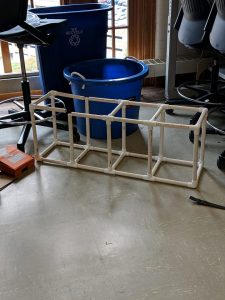
This week, I built part of the scaffolding. We, unfortunately, ran out of the joints needed to build the rest of the scaffolding. You can see that current status of the scaffolding in the picture below:
In addition, we did get in our power supplies and were able to test out the valve, which worked as expected. I also worked on the design for the mixing station this week. Below is a drawing of what we expect to put together.
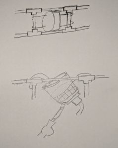
Essentially, the most of the motor that we took apart from the magnetic mixer stirrer is still intact. We will glue the platform that holds the magnets to the bottom of the beaker. From there, we will suspend the beaker in air using metal wires (such as chicken wire). This should allow us to stabilize the mixing motor and the beaker. We will also have a ring of wire go around the top of the beaker to stabilize. In addition, we will drill a hole in the bottom of the beaker to allow liquid to flow out. We will use an adapter to connect the silicone tubing to the valve and the beaker.
For this upcoming week, I will go to Home Depot to purchase some more of joints that we need for our scaffolding. We will also purchase the metal wiring needed for the mixing station. We should be able to implement the rest of the scaffolding and the mixing station by the end of this upcoming week.
David:
For this week, I worked on cutting out the PVC piping and designing/testing the mixing station with Connor.
Moreover, since the power supply came in, I was able to connect the power supply to the hat and program the hat to drive the big pump that we are going to use for rinsing system for certain amount of seconds. I still get I/O error sometimes when driving the bigger pump, and I couldn’t figure out the reason. After reading the specs of the pump and the hat, I think the reason might be the overheating with the chip on the hat. Since our system won’t be in use all the time and the pump was working properly in most of my testings, I think it wouldn’t be an issue in the end.
With some testing, I think we would pump enough water with the bigger pump to rinse off the residue in less than 2s.
For next week, I would prepare the mid-semester demo with the team and start working on the database.
Overall:
At this point, we only have $61 left to purchase parts for our project. While we have purchased most of the parts that we need for our project, that will most likely not cover the rest of the parts that we need to make the project a success. However, we have agreed as a team that we pool from our own money to purchase any additional parts. One thing that we have to address is how to slow down the spinning of the magnetic. We used to be able to control the speed of the spinning of the magnet using a potentiometer. However, the potentiometer broke off once we were trying to get it loose from the casing that the motor was in. We can solder on a potentiometer or a resistor to the motor such that there is less current flowing through the system. On the other hand, we could manually add some kind of weight to the spinner to make it spin slower. While we have laid out these various options and the implementation should be minimal, we need to make a decision in the next couple of weeks. With regards to the overall schedule, we don’t need to make any major change to the schedule and are still on track to complete everything that we need for the project.