Luca’s Status Report 4/6

This Week

This week I finished assembling the stage, and wrote code for the steppers. The remaning assembly included: boring out larger holes in the aluminum belt clamps, sanding down said clamps, wiring together the limit switches, and setting up the electronics for the motor drivers. However, the bulk of my time was spent on the code. The code has a handful of key features I’ll list here:

  • CLI (command line interface) to allow both a user and another arduino to directly and intuitively control the steppers. This includes reading (harder than you’d expect) the serial in a coherent way, parsing it, then issuing commands. This also included testing if it’s actually possible to communicate between arduinos via serial, which it is.
  • Backend driver that converts stage x y coordinates into motor steps. This way the user can issue a simple command via serial “goto 100,200” and the stage will simply go to that coordinate. The stage is around 10000 by 7000 steps if I remember correctly. Doing some rough math, this results in an accuracy of 550mm / 10^4 ~ 0.055 mm/step = 55 microns per step.
  • Homing code to measure how large the stage actually is, and what the backlash of the stage is. However, after implementing this, it appears it may not be necessary. I designed and build a stage that is so mechanically robust and rigid that the belt never slips, and thanks to steppers always moving the same amount per step, does not need calibration. A one time measurement of max stage size is sufficient. This drammatically reduces the wiring complexity as we don’t need to worry about extra wires from the limit switches getting in the way of the stage. However, because all of this code is already written, we may wire up the limit switches anyway as we need to cable route the charger’s main cable anyway.
  • RPM and duty cycle interaction with the motors, so the user can specify a specific speed in rpm and a duty for the motors. I also found the reliable speed limits of the steppers, as going too high or too low results in skipped steps and stalling. The code to prevent the user from doing this is included. I also attempted to characterize the affect of duty cycle on the motors, but found no real trends. I think our motors and drivers are voltage limited with more than enough current. As such, increasing or decreasing the step duty didn’t have much of any affect.

Schedule

I believe we are on or ahead of schedule.

Next Week

Anirud’s Status Report for 04/06

This Week:

Worked with Callum and Luca to expedite the integration of the mechanical and electronic subsystems for the interim demo.

I soldered and implemented the limit switches for the motor rails with Luca.

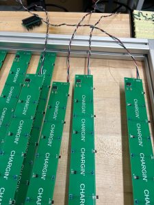
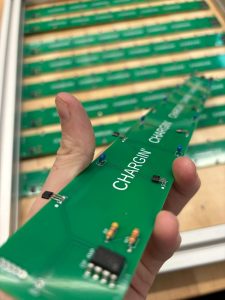
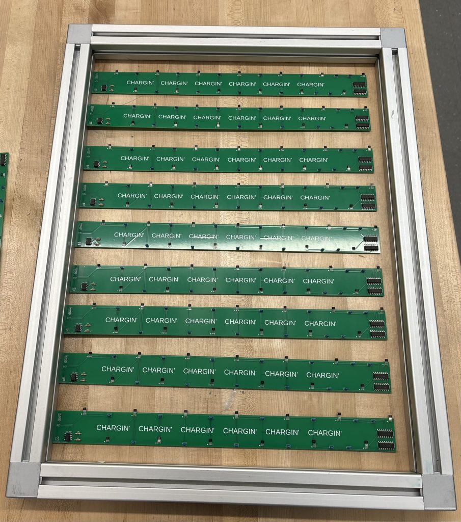
I brought the wood back from Home Depot, stenciled and cut it to size for the top surface of our table.

As for the charging subsystem, I ordered and received the new, more precise ammeters. I have now validated that we are able to reliably detect devices (both phones and earbuds) and the detection is fast enough for us to use the motors to do fine positioning of the coil under the devices. I ran into a problem, where I saw the current bouncing around a decent amount. This does not really impact detection of devices, since I can take an average of values over a given timeframe to minimize the effect this has. However, this might affect the detection speed and possibly other things like charge state selection down the road. I need to hook up the ammeter to a scope to see if it’s a data acquisition rate limitation f the Arduino, and I am looking at some aliased data or if it is something else.

Schedule:

No changes to the schedule this week. I believe we are on track, if not ahead. We presented an updated Gantt chart during the interim demo and will try to post a picture of it in the Team Report.

Next Week:

We need to etch channels into the wood for proper placement of the PCB’s. Luca is going to be leading this, but I will be helping him. Once this is done, I will also be mounting the PCB’s onto the wood with Callum. I will also be mounting the wood itself on the frame; we need to figure out if we are going to use 3D printed components or long screws.

I am going to be working closely with Luca to integrate the ammeter sensing code into the motor control code for fine positioning. We need to figure out what pattern we are going to be doing to scan the general detected device area and how fast we are going to do this. Once I figure out what is going on with the current measurement, I am going to look into implementing charge state selection. Callum and I also need to work on the code: 1. that will store and sequence the detected devices and 2. that will use Hall Sensor data to interpolate the relative location of the device with respect to the nearest sensors, to get better racy.

Now that we have a decent amount of components/subsystems built, we are mostly going to be working on integration, adding final touches, and going beyond MVP.


Verification Tasks:

Limit Switch Testing:
– Confirm the correct operation of the limit switches installed for motor rails.
– Record any instances of switch failure or inaccuracy and troubleshoot as needed.

Charging Subsystem Efficiency Check:
– Verify the charging system’s ability to accurately detect various wireless charging devices.
– Assess the time taken for device detection and the system’s response time.

Ammeter Performance Analysis:
– Examine the readings from the new ammeters, focusing on stability and precision.
– Determine how fluctuations in current readings impact the efficiency of the charging process.

Subsystem Integration Evaluation:
– Conduct tests to assess how well the charging system integrates with the mechanical and electronic subsystems.
– Evaluate any synchronization issues between the charging mechanism and the table’s movements.


Callum’s Status Report for 03/30

This Week
  • Worked on Arduino sensing code and made it compatible with multiple analog inputs.
  • Created a running average matrix system for the sensing code
  • Wrote a Python script which took in serial inputs and output a heatmap with sensor values to allow for easy debugging of the sensing system.
Current Schedule

Currently on track after quick PCB ordering and assembly. Luca is working on motor code – I will help integrate this next week.

Next Week
  • More code for sensing and coordinate generation
  • Integration with Luca
  • Work with Anirud on linking with Ammeter for charging status for use in UI


Anirud’s Status Report for 3/30

This week

I successfully completed assembling the Sensor Matrix PCBs’ wiring. We encountered a challenge when we discovered that the pin header we used in Fusion 360 had a different pitch than expected. To solve this, we created our own braided wiring, ensuring both rigidity and effective electrical contact. Additionally, the Arduino ammeter modules arrived, leading me to splice our wiring cable for the wireless charger and begin testing. My tests focused on several aspects:

– The speed at which the charge current is detected after placing a device on the charger.
– How quickly the current decreases once the device is removed.
– The variation in current as the device continues to charge.
– Differences in the charge current curve for various devices (phones, earbuds, etc.).
– The occurrence and timing of the charge current plateau and the device’s charge state at that point.

During testing, I noticed that our charge current never exceeded ~2.5A, while our module was designed to measure up to ±30A. This limitation resulted in poor resolution for small currents. To address this, I found and ordered a new ammeter module with a maximum range of 5A and significantly improved resolution.

For the table’s top, I decided on the material in collaboration with Callum and Luca, and placed the order through Quinn.


Schedule

It appears the entire team is back on track. We have nearly finished the mechanical subsystem and most of the electronics. Our next steps involve adding final touches for the system integration of all components and then incorporating features to elevate our project beyond the minimum viable product (MVP), such as screen integration and selectable charging modes.


Next week

My focus will shift to working on the wood surface for the table’s top. This involves cutting it to the right shape, ensuring proper measurements, and providing adequate support around the frame’s edges. We might need to use 3D printing or screws for this. Depending on the wood’s thickness, we may also etch channels into it.

Additionally, I’ll collaborate with Callum on sensor integration to complete the sensing mechanism before the Interim Demo. This involves assembling all components and integrating the cables with our frame. We may also design a 3D-printed lip that attaches to the frame to secure the electronics.

Once these tasks are completed, I will start testing the charge current with the new, more sensitive ammeters.

Team Status Report for 3/30

Current Risks:
  • A significant number of soldered components are faulty on the PCB
  • Arduino Ammeter does not work as we expect
  • Interfacing the two arduino is not as straightforward as we expect
  • We have issues with the physical placement of PCBs underneath the tabletop surface, which will make the charging of devices more difficult. In line with this, we also need to carefully choose what the clearance of the charging coil will be under the PCBs, which need to be sanded down to be made smooth.
  • Sensors aren’t as accurate as we expect and triangulation of devices is difficult
Schedule Changes:

No schedule changes to report this week

Design Modifications:

No changes thankfully

Luca’s Status Report for 3/30

This Week:

This week I was finally able to fully assemble and test the stage (images and video at the bottom of this post). My meticulous modeling and dimesioning resulted in every single part being perfect and the entire assembly working right away. The only modifications I had to make was the holes I left for screws being a bit too small because of the printer’s kerf and thermal shrinking. But that was quickly resolved with a drill and a few bits. It was honestly immensely satisfying to see the whole assembly working perfectly after spending so many hours in solidworks and assembling it all.

As for the belt, that was a bit more problematic. For some reason, there is far more resistance to movement than I was expecting. After some debugging, I couldn’t find any indication of why this may be. My leading theory is that while each roller might have low resistance, all 8 together plus the magnetic resistance of the steppers results in a much larger total force. Regardless, the entire assembly is very sturdy, enough to resist the motors attempting to drive past the limits of the stage. The steppers also have far more than enough torque to easily overcome the friction on the belt.

Schedule:

If I can get the motor code fully working by next week, we will be well on schedule to completing our MVP the week after carneval. Now that I’ve seen how strong my parts are, I also don’t think there is much risk of mechanical failure. I also made sure to buy and print at least one spare of every single component that’s not metal so we should be totally fine even if something breaks.

Next Week:

As I aluded to in the last paragraph in the first section, I’ve also started writing code for the steppers. My plan for next week, once the limit switches arrive, is to finish the code on the uno. That will include: basic coordinate translation, homing, and calibration. I also plan to do a stress test once that is all in place to see if fans are actually necessary. While writing the code, I was running the steppers at a respectable 400RPM and neither the steppers nor the drivers got especially warm.

Time allowing, I also plan to try and interface the two arduino: the mega controlling the sensors and the uno controlling the motors. Should that work as it should, we may even have movement to detected devices done by interim demo.

Media:

Manual movement of the belts to simulate the motors moving. Next week I’ll have videos of the stage moving via the motors.
https://drive.google.com/file/d/1Pu_YjtrhgJjbOOEIajq9W80HExhFK8x3

Anirud’s Status Report for 03/23

This Week:

  • Assembled and soldered PCBs with help from Callum (Took a while! But quicker than expected!)
  • Acquired the ammeters for the charging subsystem and ran some preliminary tests to verify functionality
  • Finalized wire management topology for PCBs to Arduino with Callum.
  • Figured out where to 3D print our parts (for free!) with Luca.

Current Schedule:

I believe that we are ahead of schedule, at least on the electronics side, since we could get the PCBs done in 2 days. We are still running a little behind on the mechanical integration due to unexpected issues, but we should be back on track with that soon!

Next Week:

  • Finish code for the charging circuit.
  • Finalize the wiring topology and cable management for the charging circuit.
  • Sanding down the bottom of the PCBs to ensure smooth movement of the charger and gantry.
  • Helping Luca and Callum with the mechanical integration. We will need to finalize the material that we are going to be using for the table-top, so that we can laser etch indents for the PCBs to be flush with the underside of the table-top.
  • I am also going to look into integrating the charge current for finer location sensing and integrating that with the gantry code. However, this will probably bleed into the week after.

Callum’s Status Report for 03/23

This Week:
  • Assembled PCBs with Anirud
  • Expanded sensing code for multiple arrays
  • Created an interconnect board to link PCBs with Arduino Mega
  • Verified PCB dimensions with respect to the table frame
Current Schedule:

PCB assembly went faster than expected and little troubleshooting was needed for the code – this has helped us to get back on schedule. This week I plan to catch up with Luca to talk about the schedule for the mechanical assembly part of the project – from here we can plan how to divide up work for the motor control code.

Next Week:
  • Start integration between motors and sensing
  • Begin writing motor control code with Luca
  • Begin writing charging code with Anirud

Team Status Report for 03/23

Current Risks:
  • Motor control is not as straightforward as we think for H-belt design
  • A significant number of soldered components are faulty on the PCB
  • 3D Prints fail or are unable to handle stress of motors
  • Motors are weaker than advertised
  • Arduino Ammeter does not work as we expect
  • We have issues with the physical placement of PCBs underneath the tabletop surface, which will make the charging of devices more difficult. In line with this, we also need to carefully choose what the clearance of the charging coil will be under the PCBs, which need to be sanded down to be made smooth.
Schedule Changes:

No schedule changes to report this week

Design Modifications:

None this week!

Luca’s Status Report for 3/23

What did you personally accomplish this week? Give files or photos that demonstrate your progress. Prove to the reader that you put sufficient effort into the project over the course of the week (12+ hours).

I finalized the CAD using the dimensions I got from last week. I’ve been printing parts for the assembly since, which has been quite time consuming as the printer I’m using is having z homing issues. Aside from that, going back and forth to start check, clean, and assemble parts has been both cumbersome and time consuming.

Is your progress on schedule or behind? If you are behind, what actions will be taken to catch up to the project schedule?

While I won’t have everything fully printed by saturday night, I will by mid next week. Assuming all the parts I designed work, I will be on schedule. However, for each part that fails or needs redesign, it will push me further and further back.

What deliverables do you hope to complete in the next week?

Fully assembled and tested mechanical stage. Stretch goal is to have the arduinos connected with the help of Anirud and begin driving the motors.