Skip to content
Team A5: Chargin'

Team A5: Chargin'

Carnegie Mellon ECE Capstone, Spring 2024

  • Luca Garlati
  • Anirud Durani
  • Callum Bagnall
  • Team
Author CallumPosted on April 27, 2024No comment Callum’s Status Report for 04/27

Callum’s Status Report for 04/27

This Week:
  • Troubleshooted the sensor matrix with Anirud
  • Tested using a standalone power source for the matrix rails (we found that we were current limited by the Arduino 5V pin)
  • Wrote some code for finding the largest change in sensor output (will be used for detection)
  • Completed the final presentation
  • Made plans for final project integration during this weekend and next week
Next Week:
  • Integrate all modules of the project
  • Prepare for final demo day
  • Complete demo poster
Scheduling:

As I spoke about during the final presentation, we are somewhat behind schedule due to troubleshooting efforts on the sensor matrix, but we have mostly solved the problem as of today. We still expect to be ready for demo!

Categories: Callum Bagnall's Status Reports
Author aduraniPosted on April 27, 2024April 27, 2024No comment Anirud’s Status Report for 04/27

Anirud’s Status Report for 04/27

This week:

I encountered several challenges while debugging the Sensor Matrix. After identifying and fixing a short in the mux-select lines and re-wiring, I individually tested all the PCBs, which showed promising results. Callum revised the heatmap code to include interpolation. However, when I assembled the components together, the accuracy plummeted by about 80%, and visibility at most locations was severely compromised. Despite functioning perfectly outside the circuit, the components failed to perform once integrated. Additionally, the sensitivity of the hall sensors significantly decreased.

In response to these issues, I ordered new digital hall sensors to see if they might help resolve any of the ongoing problems. To troubleshoot further, I initially reduced the polling rate, using the Arduino’s baud rate to control sensor queries for real-time imaging. This adjustment, aimed at minimizing potential interference from rapid mux switching, unfortunately did not resolve the issues.

I then examined the Arduino’s power supply, suspecting that high system impedance might be dampening sensor sensitivity. By connecting the matrix to an external power source and unifying all GND pins, I tried to enhance performance by cautiously increasing the voltage while maintaining low current compliance—yet this approach also fell short.

However, a breakthrough occurred after a revelatory dream prompted me to adjust the current compliance in tandem with the voltage increase, despite the Arduino not being directly powered by the current. This adjustment proved successful, though the reasons behind its efficacy remain unclear, particularly since the system’s operation isn’t reliant on current. I plan to further investigate this anomaly. This solution did introduce some additional noise, which I intend to mitigate by soldering larger capacitors onto the power lines.

Moving forward, the matrix will be powered externally, ensuring optimal voltage and current levels. Luca has already procured the necessary supplies, and I will maintain a unified ground across the system. I am also experimenting with Op-Amp resistance values to potentially enhance amplification.


Schedule update:

Despite a slight delay due to these troubleshooting efforts, I am close to being back on track.


Next week’s agenda:

– Test the new digital Hall Sensors to determine if they address the matrix issues.
– Continue adjusting resistor values for the Op-Amp.
– Solder larger capacitors onto the power lines.
– Secure wiring and integrate with DC power supplies.
– Assist Luca with mounting the sensor matrix.
– Support Callum in developing the FSM for the system.
– Prepare for the Final Poster and Demo.


Categories: Anirud Durani's Status Reports
Author LucaPosted on April 27, 2024April 27, 2024No comment Team Status Report for 4/27

Team Status Report for 4/27

Current Risks:
  • More problems arise upon integration of all project modules
  • Catastrophic failure of a component or set of components before demo
  • Damage to PCBs or Arduino’s during capacitor soldering or voltage testing
Schedule Changes:

No schedule changes this week

Design Modifications:

As Anirud explained in his post, we are planning to possibly change resistor and capacitor values on our boards. We currently have an amplification of around 5/3 on the op-amps and coupling capacitors set at 100 micro farads. We are aiming to increase these values due to the increased voltage we intend to emplace on the matrix system.

List all unit tests and overall system test carried out for experimentation of the system.

Matrix:

  • Testing individual sensor performance (V/mm for device placement)
  • Testing single PCB performance
  • Testing overall matrix performance
  • Testing polling rates for the matrix (col/ms)
  • Testing voltage levels on matrix power rails
  • Matrix power consumed

Ammeter/Charger:

  • Amperage through charger with respect to device distance
  • Total minimum and maximum amperage values
  • Testing how amperage changers as device charge increases
  • Maximum charging distance and efficiency

Gantry:

  • Speed limit testing: How fast we can safely operate the gantry
  • Torque limits: In hand with speed, how much power we can safely operate with
  • Time testing: The longest and average time for the gantry to move to a position

System:

  • Total Latency: The total time taken between device placement and charging
  • Total Accuracy: How close we can predict device location using all modules
List any findings and design changes made from your analysis of test results and other data obtained from the experimentation.
  • We found charging distance to have a maximum of around 2cm, giving us more leniency in PCB and top panel sizes. We used this information to save budget by not purchasing thin/flexible PCBs
  • Whilst testing the power consumed by the matrix, we found that we were limited by the Arduino’s available amperage. This led to our decision to use an external source to power the matrix. Through this testing, we also experimented with using higher voltages through the system which gave us a higher sensing accuracy – we plan for our final implementation of the matrix to run on 5.7V.
  • Through testing matrix and ammeter accuracy, we found that the former was less accurate than expected, whilst the latter was far more than expected. Using this information, we changed our design for software to use the matrix to find general location, and the ammeter to precisely find the location given the matrix prediction.
  • We found that our total latency was bottlenecked by the gantry system and was minimally impacted by the low polling times we were able to achieve from the matrix. From this information, we decided to minimize polling times as much as possible for the final build.
Categories: Team Status ReportsTags: status report
Author LucaPosted on April 27, 2024April 27, 2024No comment Luca’s Status Report for 4/27

Luca’s Status Report for 4/27

This Week:

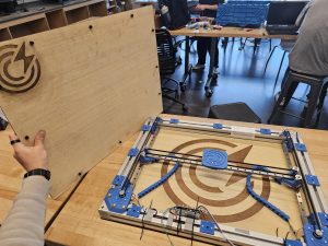
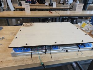
This week I put the finishing touches on the gantry. This mainly included laser cutting wood and attaching it to the frame. While this sounds trivial at worst, it unfortunately wasn’t.

First, we didn’t buy enough wood. The 4x4ft sheet was a hair too short to get a third cut: 4ft ~ 122cm and our longest dim for the footprint is 69cm, so we were just 16cm short. As such, I needed to go and find where I could buy such an awkward size of wood. Techspark only sells 1x2ft increments, which are far too small, and going through home depot again would have been a headache between picking up, and cutting down a 4x4ft sheet again so it could fit in the laser cutter. Further, this would eat into the last remaining pennies of our budget and be super inefficient (54*69 / 122^2) = 25% used of the whole sheet. Thankfully, after bothering Ed (Techspark guy) enough, I was able to scavenge a 2x3ft sheet of a very similar wood to what we already bought.

Second, laser cutting / engraving large patterns takes forever. The top panel with only the small logo in the corner took 10 minutes, and the base with a lower resolution etch took 30 minutes. The whole time I had to stand watching the laser cutter, so couldn’t do anything else.

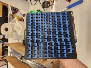
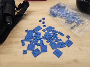
Third, because we are attaching this wood to the frame, I need inserts. However, the inserts I printed are out of the rails, and the only way to get them into the rails is to disassemble a large amount of the frame, as well as reseating the belt. And to make things worse, I had to stop working and come back to do the baseplate after the top, so I had to do the whole disassembly twice ;-;. Thankfully, nothing broke, but it took several hours to get that done.

Lastly, there were no screws long enough to properly raise the top plate off the stage. After much scavenging through techspark, I found a bunch of 8cm long imperial bolts. However, there were two problems with them. First, they were too wide, so I needed to widen several dozen holes through various parts to get the new bolts to fit. Second, they were shanked bolts (there’s a smooth section between the head and the start of the threads). In this case, it was about half shank (4cm shank, 4cm threads). So my original plan to just use a nut to hold the top wood up wouldn’t work. After much testing, I found that using hotglue to gum up the holes in the wood and then shoving the bolt in while the glue was still warm caused enough friction to hold the bolts in place. At least, well enough. So after 30+ minutes of just hot glueing and bolting holes, I had the top board done.
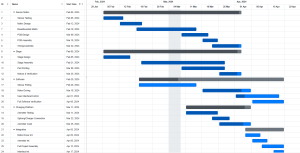
Schedule Changes:

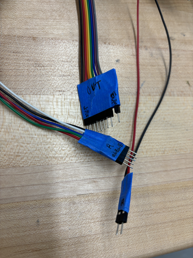
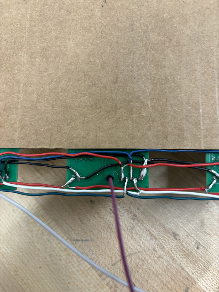
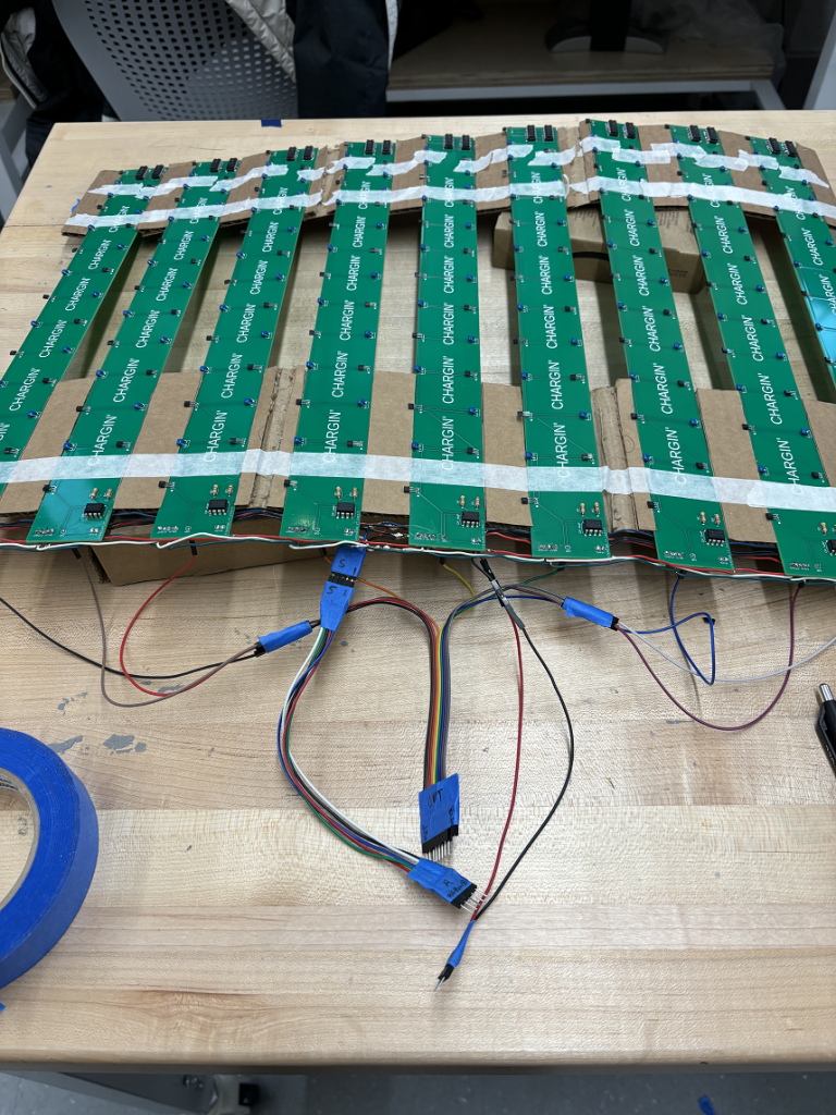
Not enough time left in the semester to really have a schedule. As of right now, I’m basically done with everything I needed to do. I’m just waiting on Cal and Anirud to finish the sensor array, at which point I will assist with final assembly.

Next Week:

I’ll assist with final assembly once the sensor matrix work.

Categories: Luca Garlati's Status ReportsTags: status report
Author CallumPosted on April 21, 2024No comment Callum’s Status Report for 4/20

Callum’s Status Report for 4/20

This Week:

Debugging and troubleshooting: Lots of it.

This week, Anirud and I encountered significant problems with reading Arduino values. After wiring and rewiring, many of these problems were solved – they likely stemmed from poor solder connections which we replaced with jumper cables. The debugging code I wrote also had some minor bugs which led to crashes and missed outputs from the Arduino.

After fixing this code, I realized that we are still having problems detecting devices on the matrix – this is on the schedule for Anirud and I to solve ASAP on Monday.

Apart from this, I mounted the matrix PCBs into a wooden cast which will be part of the final build. This mount ensures that PCBs are properly spaced and reduces strain on the components from transit and storage for now. I have taken a look at inter-Arduino communication so that we will be ready for MVP and I expect us to see communication between the matrix and motor assembly within the week.

Current Schedule:

Currently on track – but running out of time for troubleshooting the matrix.

Next Week:
  • Finalize and solve matrix problems
  • Successfully move stage based on matrix output
  • Finalize Device map code and feedback
  • Complete Final Presentation
Categories: Callum Bagnall's Status Reports
Author aduraniPosted on April 20, 2024No comment Anirud’s Status Report for 4/20

Anirud’s Status Report for 4/20

This Week:

This week, we encountered several challenges with shorts in our connections due to initial wiring issues. After multiple revisions, we’ve successfully improved the setup. The small wires extending from the top and bottom of the PCBs are now connected with jumpers, allowing for daisy-chaining in both left and right directions. This design reduces the risk of shorts, as the interconnecting wires are not soldered directly to the boards, providing more space and flexibility.

We received additional PCBs from JLCPCB and addressed wear from the soldering and desoldering processes on the original boards by acquiring new parts and soldering more units.

I also completed enhancements to the ammeter sensing code. Initially, the readings were unstable due to noise, but after implementing a moving average algorithm, the data stabilized. Verification with a laboratory oscilloscope confirmed the ammeter’s accuracy. Adjustments to the baud rate and sample count further optimized the balance between measurement speed and precision.


Schedule:

No changes to the schedule; progress is on track.


Next Week:

Next week, I’ll collaborate with Callum to address issues in the Sensor Matrix code and refine our sampling techniques.

We plan to finalize and secure the wiring for the PCBs.

Additionally, Callum and I will focus on building the Finite State Machine (FSM) and integrating it with the subsystems’ code. Post-MVP, we aim to enhance the system with further code modifications to expand its capabilities.

Categories: Anirud Durani's Status Reports
Author LucaPosted on April 20, 2024April 21, 2024No comment Team Status Report for 4/20

Team Status Report for 4/20

Current Risks:
  • Cables aren’t resilient enough and begins shearing. Debugging this would be very difficult as they are long cables.
  • The arduino and other hardware doesn’t fit in the allotted space
  • we run out of wood and have to scavenge something else to use
  • Wiring Instability: Despite improvements, the wires not being soldered directly to the PCBs might lead to connections loosening over time, particularly under physical stress or movement.
  • Short Circuits: Even with the revised setup, the risk of short circuits remains if wires are exposed or poorly insulated.
  • Component Wear: Repeated soldering and desoldering can degrade PCB components and connections, potentially leading to failures.
  • Software Bugs: Modifications to the ammeter sensing code and other software components increase the risk of introducing bugs that could affect system stability and functionality.
  • Noise and Interference: Despite efforts to minimize noise in the ammeter readings, external electromagnetic interference could still impact the accuracy of measurements.
Schedule Changes:

No schedule changes, we are on track to finish for demo day.

Design Modifications:

None as of right now, but there may be some for next week, as we haven’t truly focused on system integration yet.

As you’ve designed, implemented and debugged your project, what new tools or new knowledge did you find it necessary to learn to be able to accomplish these tasks? What learning strategies did you use to acquire this new knowledge?
We recognize that there are quite a few different methods (i.e. learning strategies) for gaining new knowledge — one doesn’t always need to take a class, or read a textbook to learn something new. Informal methods, such as watching an online video or reading a forum post are quite appropriate learning strategies for the acquisition of new knowledge.

As a team, we used a few novel tools to assist with debugging. Before we even began working on the project, we found and watched videos online about magic sand drawing tables. These have similar hardware as our table does, just without the sensing component. Being able to find and draw inspiration from projects online was a first for all of us, especially for something this large and complex. For the sensor array, using a visual heatmap was exceptionally helpful in finding faulty sensors rather than just relying on terminal printouts. For hardware, while we used no novel tools, we did have to learn how to manage large assemblies. The final assembly file in SolidWorks is upwards of 150 parts, and working on something that large brings nearly all computers to their knees. We also had to learn how to 3D print with the bamboo X1 Carbon, a printer none of us had used before.


Categories: Team Status ReportsTags: status report
Author LucaPosted on April 20, 2024April 20, 2024No comment Luca’s Status Report for 4/20

Luca’s Status Report for 4/20

This Week:

This week, I spent a lot of time printing the (hopefully) last components. This includes both the cable snakes (for routing cables to the moving gantry) and the final attachment points for the top and bottom boards. The base model for the cable snakes was taken from thingiverse (https://www.thingiverse.com/thing:3715002) and modified by me to fit our needs. The attachment components were fully modeled by myself.


Cable Snakes from Thinkgiverse (second print of 103, 130 surviving total)


Assortment of attachment points for top and bottom panels of wood. Cad model render not pictured.

Aside from printing the cable management parts, I also did cable management. The stage is now able to finish its homing sequence without ripping out any cables. While I haven’t conducted a stress test in fear of cables internally shearing, it survived around 5 to 10 homing sequences, so I think it’s sturdy enough.

https://drive.google.com/file/d/1-2zJbzIdmX5Iz3ojDe6boMGLyFxAm-lj/view
Video of stage homing sequence with cable snakes.

Schedule:

I am on schedule.

Next Week:

  • Cut out the top and bottom wood pieces
  • Attach the bottom and top plates to the assembly
  • Route the charger’s cable to the stage
  • some cable management and maybe a piece of wood to keep all the arduino and wires tucked in the safe back area
  • Assist Cal with firmware interfacing
  • Measurement of specs will likely have to occur during finals week
Categories: Luca Garlati's Status ReportsTags: status report
Author aduraniPosted on April 6, 2024April 6, 2024No comment Team Status Report for 04/06

Team Status Report for 04/06

Significant Risks and Management Strategies:
Our primary risks include technical challenges in integration, potential mechanical failures, and ensuring precise control over the moving parts. We are managing these risks through rigorous testing, collaboration, and contingency planning. Specifically, we’ve focused on enhancing communication between subsystems and refining our designs to prevent mechanical wear and tear.

Design Changes and Cost Implications:
We’ve made several changes to our design. These include implementing limit switches for motor control and modifying the power electronics for more precise ammeter readings. The changes incurred some costs, primarily in terms of additional components and time spent on redesigning certain aspects. However, we’ve mitigated these costs through efficient team collaboration and leveraging our skills in electronics and mechanical design.

Updated Schedule:
Currently, we are on track with our project timeline. There have been no significant schedule changes this week, and we intend to maintain this momentum. Our updated Gantt chart, presented during the interim demo, accurately reflects our current progress and upcoming milestones.

Progress Highlights and Next Steps:
– Anirud worked with Luca and Callum on the integration of our subsystems. This collaboration was essential for our interim demo.
– Anirud managed to implement the limit switches for the motor rails and procured the wood for the table’s top surface, cutting it to the required dimensions.
– On the charging subsystem, the new ammeters have improved our device detection capabilities, although some fluctuations in current readings require further investigation.

Next Week:
We plan to etch channels into the wood for PCB placement and mount the PCBs onto the table. Integration of the ammeter sensing code with motor control is a priority. We’re also focusing on debugging the matrix and beginning its integration with the motor system.

Conclusion:
Our project is progressing well, and we’re mostly working on integration and refinement. The team is highly motivated to go beyond our Minimum Viable Project, ensuring that Chargin’ is not only functional but also exemplifies innovation and technical excellence.


Validation:

Anirud:

– Testing for Device Detection Reliability: Verify that the charging subsystem consistently detects various wireless charging devices (phones, earbuds) across multiple trials.
– Current Fluctuation Analysis: Examine the extent of current fluctuations observed in the new ammeters and their effect on detection speed and charging performance.
– Integration with Mechanical Movements: Assess the coordination between the charging mechanism and motor movements, ensuring seamless and accurate positioning of the charging coil.

Luca:

– Motor Speed and Distance Accuracy: Conduct precise measurements of the time taken for motors to traverse the stage and the accuracy of their end positions.
– Backlash Quantification: Utilize the limit switches to accurately measure and quantify any backlash in the mechanical stage, ensuring consistent movement.
– Motor Noise Level Testing: Evaluate the decibel levels of motor noise during operation, ensuring it falls within safe and acceptable limits for user environments.

Callum:

– Sensor Response Testing: Run tests on each sensor board with a magnet to confirm they generate appropriate outputs.
– Decoding Algorithm Accuracy: Test the decoding process by manually sending specific values to the sensor matrix and comparing the Arduino outputs to expected results.
– Device Tracking and Mapping Verification: Validate the accuracy of the device tracking system by placing devices at known locations and checking if the system accurately maps and stores their positions.

Updated Gantt Chart:

Categories: Team Status Reports
Author CallumPosted on April 6, 2024No comment Callum’s Status Report for 04/06

Callum’s Status Report for 04/06

This Week:
  • Bundled cables for matrix output – this was changed on Wednesday to a hard-wired design with temporary spacers shown below.
  • Soldered PCBs together giving us a much more sturdy matrix and reducing total length of wire used to reduce crowding in the final design.
  • Added output for M2M cables – this will help us test and assemble later.
  • Tested different Baud rates for the Arduino as we were having some trouble transmitting all data to our debugging software (settled on 56.7kbps)
  • Tested continuity in new cable design to ensure secure solder connections and verify there is no short-circuits in the system
  • Discovered a possible bug or error late on Friday – some of our sensors are working properly but are struggling to properly detect devices. Anirud and I already plan to explore this problem on Monday.

Matrix breakout cables (Above)

Soldered connections, repeated 9x for each board (Above)

Total matrix as of Friday evening with temporary spacers and new cabling (Above)

Current Schedule:

Schedule looks great right now for me! The matrix and its code is mostly complete now. All that remains on this side of the project is debugging, verifying, and merging this system with Luca’s motor system and codebase.

Next Week:
  • Work with Anirud to debug the matrix
  • Begin integration with motors
  • Replace temporary spacers (possibly mounting matrix to table surface)
Categories: Callum Bagnall's Status Reports

Posts navigation

Page 1 Page 2 … Page 4 Next

Pages

  • Design Review
  • Final Project Documents
  • Project Summary
  • Proposal

Archives

  • April 2024
  • March 2024
  • February 2024

Meta

  • Log in
  • Entries RSS
  • Comments RSS
  • WordPress.org
Team A5: Chargin' Proudly powered by WordPress