Ryan’s Status Update for Saturday, Feb. 22

Termination resistors?

Since the signals going in and out of the PDM microphones are digital, termination  resistors may be needed to reduce ringing and overshoot when the signal is being transmitted over a long distance. TDK’s recommendation is as follows:

When long wires are used to connect the codec to the ICS‐41350, a source termination resistor can be used on the clock output of the
codec instead of a buffer to minimize signal overshoot or ringing. Match the value of this resistor to the characteristic impedance of
the CLK trace on the PCB. Depending on the drive capability of the codec clock output, a buffer may still be needed, as shown in Figure
13.

From: https://43zrtwysvxb2gf29r5o0athu-wpengine.netdna-ssl.com/wp-content/uploads/2016/02/DS-000047-ICS-41350-v1.1.pdf


Let’s do some quick calculations if termination resistors are required at these signal speeds. Here’s a paper that discusses when it’s necessary to put termination resistors: https://www.analog.com/media/en/training-seminars/tutorials/MT-097.pdf

The maximum PCB track length is then calculated by multiplying tr by 2 inch/nanosecond. For example, a maximum frequency of 100 MHz corresponds to a risetime of 3.5 ns, so a 7-inch or more track carrying this signal should be treated as a transmission line.

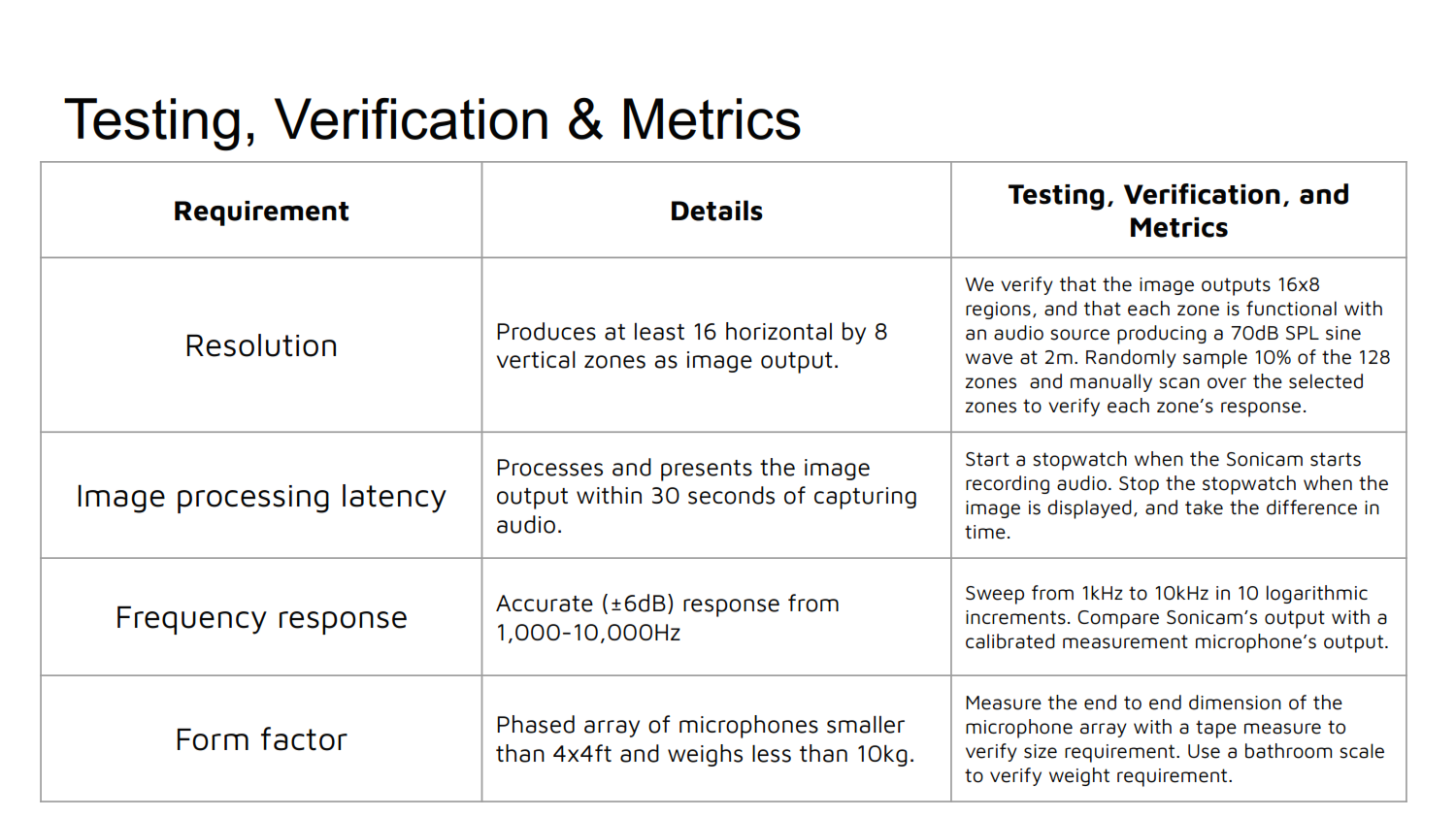
We’re driving the input clock to the PDM microphones at 3.0MHz. At 3.0MHz, the rise time is about 115ns. The dimensions of the microphone array are 1x1ft max, so the maximum FFC cable length is 1ft. 115ns * 2 in/ns is 230in, so we should be at least an order of magnitude safe without termination resistors.

  • We haven’t heard back from TDK or Knowles regarding microphone samples, so I’ll follow up next week. Even if we don’t get the microphones for free, we still do have enough budget for them. ($150 for 100 mics)
  • We will have our design review on Monday, Feb 24, so we’ll be preparing for the presentation.
  • We are on schedule so far.
  • To do: Solder wires to the microphones, power it with 3.3V and feed it a 3MHz clock. Capture the output waveform from the mic and develop a script to analyze the waveform. Low pass filtering it should yield the analog waveform.
Team Status Update for Saturday, Feb. 15

What are the most significant risks that could jeopardize the success of the project?

The largest challenge so far is:

making the final decisions on the array shape and size, as many aspects of the system will be depend strongly on this.  How are these risks being managed? What contingency plans are ready?

• Were any changes made to the existing design of the system (requirements, block diagram, system spec, etc)? Why was this change necessary, what costs does the change incur, and how will these costs be mitigated going forward?

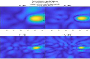
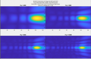
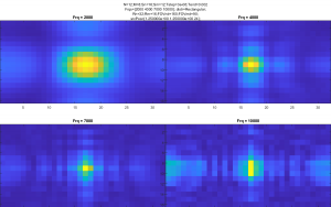
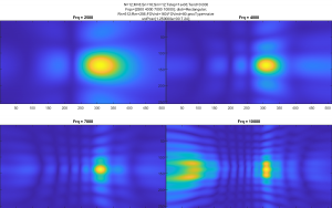
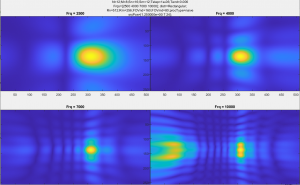
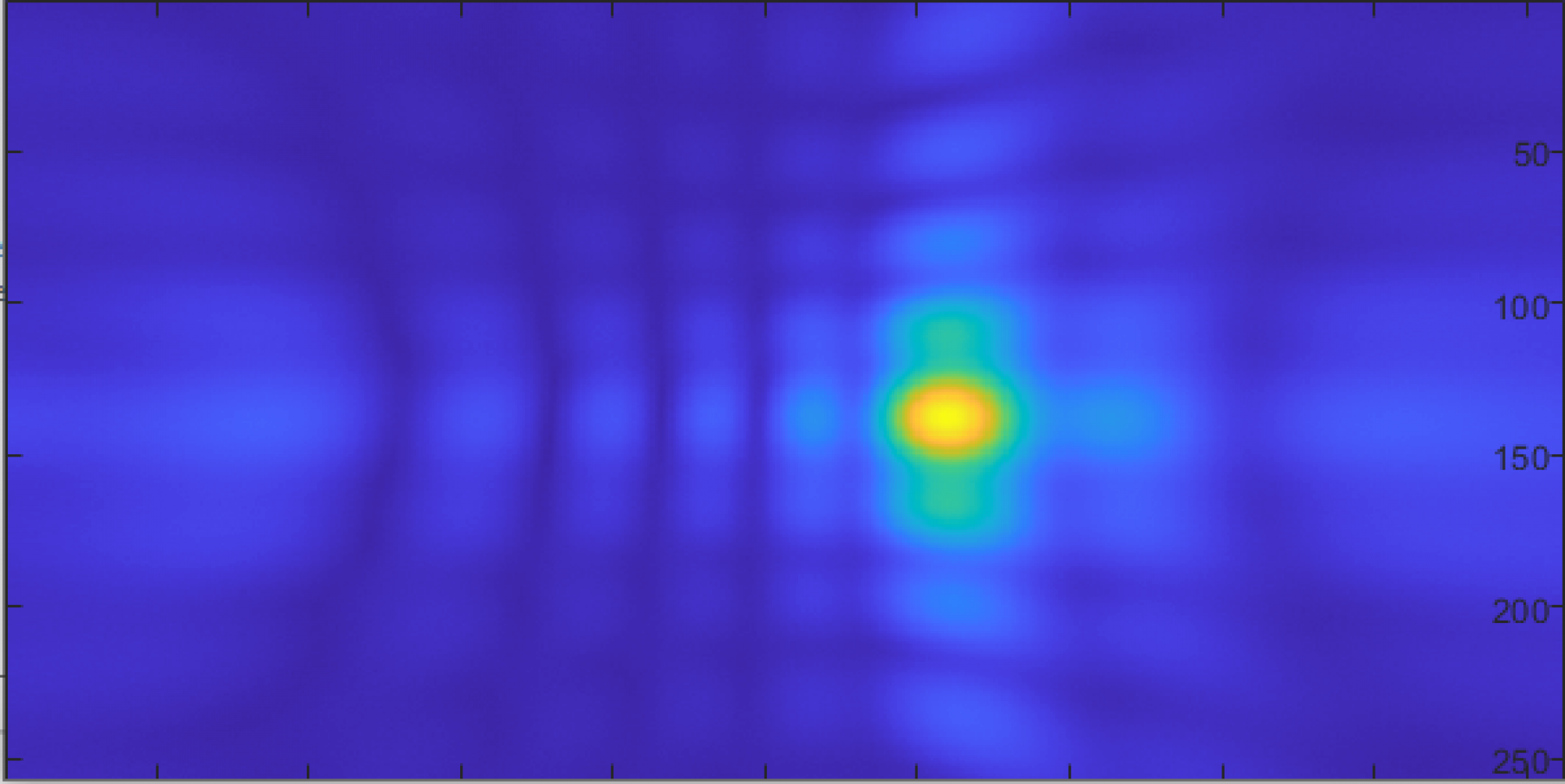
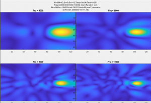
We have the results of several simulations of different array geometries, sizes, and frequencies of interest.  In all cases, they are attempting to image a scene with a single source at a specific frequency.  Plots are 4 separate images of the same scene at different frequencies, but all other parameters are the same.

Randomly distributed microphones, showing slightly reduced artifacts, but at the cost of a higher, random noise floor over most of the image

Image form microphones randomly distributed through a volume, showing nearly identical performance to the random array

8*12 rectangular array images, showing better noise performance over most of the image than the random distribution, but with distinct, clearly visible artifacts.

Early, low-resolution simulation, showing that the concept is at least viable at these sizes/frequencies.

The 10KHz image in this series shows one of the issues with higher frequencies, an artifact is visible at the left of the image, while the source is slightly off center to the right.  This artifact stays out of the field of view that we’re interested in (90 degrees), but will have to be considered in the final design.

Ryan’s Status Update for Saturday, Feb. 15

This week, we’ve evaluated candidates for PDM microphones, which take in a 3MHz clock and output a pulse density modulated digital signal, as shown below: 

Source: https://en.wikipedia.org/wiki/Pulse-density_modulation

The reason why we’re leaning towards PDM micrphones as opposed to analog microphones is because since PDM microphones output a digital signal, we don’t need preamplifiers and ADCs for the analog microphones, and they can be directly connected to an FPGA. The price difference between analog and digital microphones are negligible.  When we’re looking at about 100 microphones, reducing the number of parts greatly reduces cost and complexity.

The two main manufacturers of PDM microphones are TDK and Knowles. I’ve reached out two both companies to see if they’re willing to help us get hold of their PDM microphones. So far, their responses have been positive and willing to work with us.

The main spec that we’re looking in the PDM mics is frequency response. Because we’re interested in 2kHz and beyond, having a relatively flat frequency response is critical to our application. The frequency response information can be found in their respective datasheets. Here’s an example from TDK’s ICS-52000:

Source: http://43zrtwysvxb2gf29r5o0athu-wpengine.netdna-ssl.com/wp-content/uploads/2016/05/DS-000121-ICS-52000-v1.3.pdf

Notice how after 5kHz, the amplitude starts rising and peaks at 12kHz at 18dB. It drops precipitously after that. This is an example with a poor frequency response. This may be good enough for cellphones where frequencies above 8kHz or so are not transmitted, but isn’t ideal for our application.

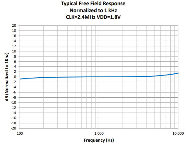
Here’s the SPH0641LU4H-1 from Knowles. It has a slightly more well behaved frequency response at higher frequencies:

We’ve ordered a sample of of microphones to further investigate their characteristics and identify areas of focus regarding these microphones.

We are on schedule.

To do next week:

Continue communication with Patrick from TDK regarding PDM mics from them as well as logistics. (QTY and shipping to us or the PCB fab)

Receive PDM microphone samples and solder and interface them with MCUs or FPGAs for testing.

Start designing the PCB for microphones. Draft a list of auxiliary components for the mics. (Termination resistors, decoupling caps, LDOs)

Introduction and Project Summary

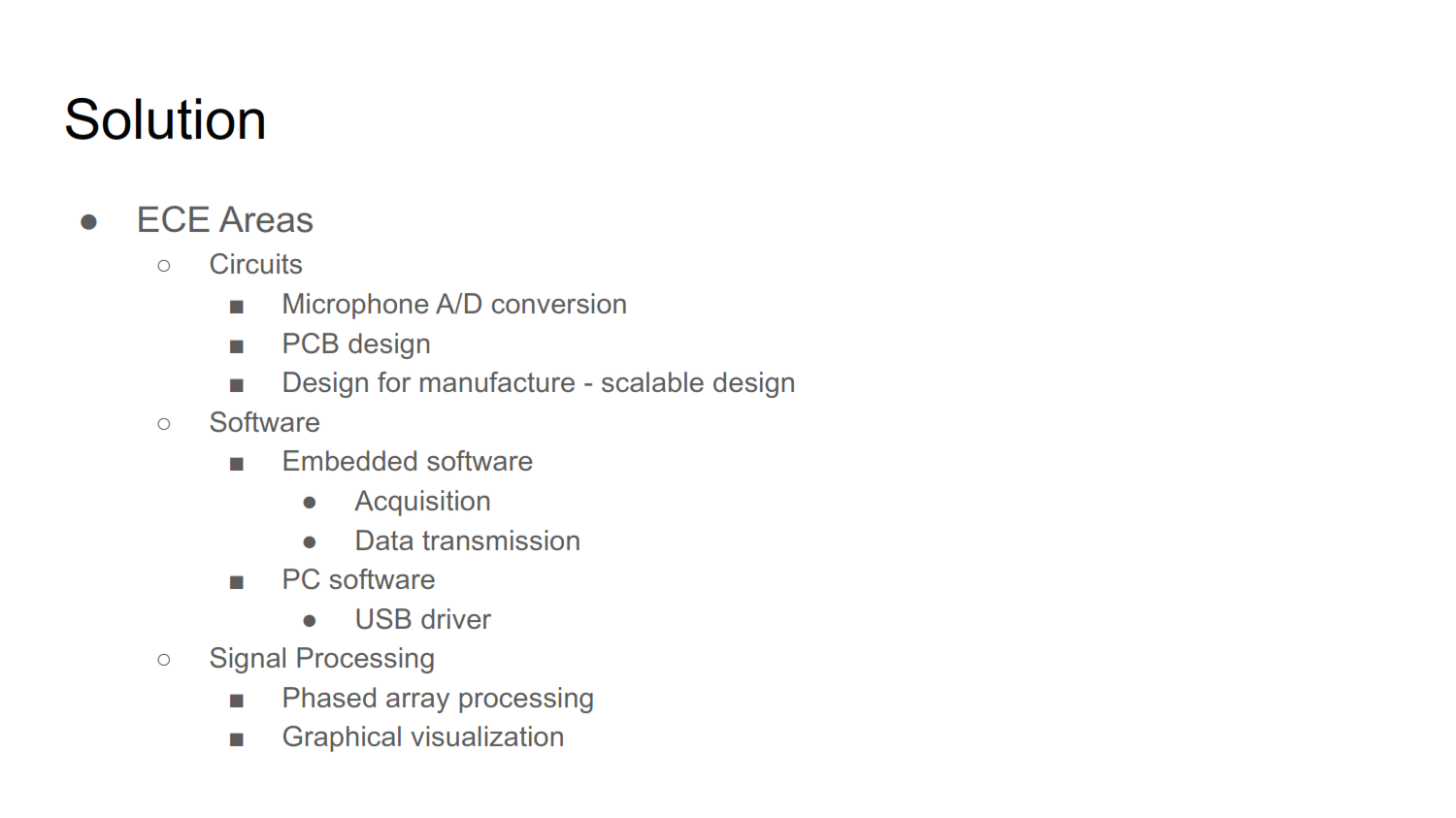
Sonicam is a tool to visualize sound. It’s like a thermal camera, but for sound. It uses an array of microphones to capture and process sound to display a heatmap of sources of noises. Humans are much better at perceiving direction using their eyes instead of sound, so we hope Sonicam would help people identify and pinpoint noises quickly. One use case for this is in detecting gas leaks. Because gas leaks have a specific hiss that can be hard to pinpoint the direction by ear, Sonicam could help quickly locate the source of the leak.

PDF: Proposal Presentation