Shravya’s Status Report for 12/07/2024

This week, significant effort was spent implementing UART communication between the STM32 microcontroller and an external system, such as a Python script or serial terminal, to control solenoids. The primary goal was to parse MIDI commands from the Python script, transmit them via UART, and actuate the corresponding solenoids based on the received commands.

  1. Description of Code Implementation:
    • The UART receive interrupt (HAL_UART_RxCpltCallback) was set up in main.c to handle incoming data byte by byte and process commands upon receiving a newline character (\n).
    • Functions for processing UART commands (process_uart_command) and actuating solenoids (activate_solenoid and activate_chord) were written and tested.
    • The _write() function was implemented to redirect printf output over UART for debugging purposes.
  2. Testing UART Communication:
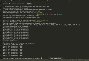
    • Python script (send_uart_data) confirmed successful transmission of parsed MIDI commands. See screenshot. This implies my computer is sending the data correctly but the STM32 is not receiving it properly.
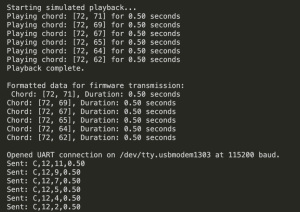
    • Minicom and other terminal tools were used to TRY to verify whether UART data was received on the STM32 side. They did not work because I can’t monitoring/”occupy” the port without inhibhiting the data being sent. It seems that sending data and monitoring data on that port are mutually exclusive. This makes sense, but I saw online that monitoring a port with a serial terminal was a common way that people debug communication protocols. I also don’t see any point in monitoring a port other than the one the communication is occurring on.
  3. Unexpected and oddly specific solenoid activation:
    • Observed that solenoids 5 and 7 actuated unexpectedly at program startup. This happened multiple times when I reflashed. Also, the movements were somewhat intricate and oddly specific. Solenoids 5 and 7 SIMULTANEOUSLY turned on, off, on (for shorter this time), off, on and off. This makes it seem as if I hardcoded a sequence of GPIO commands for solenoids 5 and 7 which I most definitely did not.
    • Added initialization code in MX_GPIO_Init to set all solenoids to an off state (GPIO_PIN_RESET).
    • Temporarily disabled HAL_UART_Receive_IT to rule out UART-related triggers but found solenoids still actuated, indicating the issue may not originate from UART interrupts.

I have been debugging this for a week. Initially, there were a few mistakes I genuinely did make (some by accident/oversight, some by genuine conceptual misunderstanding): I realised I had to explicitly flush my RX buffer, create a better mapping system from my python code which deals with an octave of notes that are called “60-72” (because this is MIDI’s convention) and I had to map them to the 0-12 numbering system I use for my solenoids in the firmware code. I also noticed one small mismatch in the way I mapped each solenoid in the firmware code to an STM32 GPIO pin. Also, the _write() function was implemented to redirect print() over UART for debugging purposes.

I now feel like I have a good conceptual understanding of UART, the small portion of autogenerated code that stm32cube ide generates (this is inherent to the way stm32cube ide does some clock configurations, it’s necessary and there is no way to stop this), and any additional functions I’ve written. I definitely knew far less when I started testing out my uart code a week ago. Yet, I am still stuck. I might be out of ideas on what component of this code to look at next. I’ve now shared my files with Peter who may be a fresh set of eyes, as well as a friend of mine who is a CS major. I have an exam on Monday, but after it ends, I will work on this in HH1307 with my friend until it functions. I need it to work before our poster submission on Tuesday night and video submission on Wednesday night.

Shravya’s Status Report for 11/30/2024

This week, I successfully handled the MIDI parsing of chords and rest notes. I can now say that the MIDI parsing is fully functional. I also completed the core implementation of UART communication, which required updates to both my Python code and STM32Cube firmware code. In Python, I added functionality to parse MIDI files and send formatted commands (e.g., notes, chords, and rests) to the STM32 over UART. On the STM32 side, I integrated UART reception code to parse incoming data and trigger the appropriate solenoid actuation logic. I met with Fiona today (Saturday) to try to get this all working on her laptop as that is the local machine we will be using in our final demo. One trivial issue that wasted about an hour of our time is that the USB to USBC converter is weak and only works when the cord is positioned at a very specific angle. Another hour and a half was spent on true debugging. Later in the night, I bought a new USB-USBC converter.

I will be the one presenting at the final presentation and I spent several hours reciting (including in front of parents + friends) and memorising my script. We set an early deadline for ourselves to submit the slides (4 pm) so that I’d have plenty of time to practice. In addition, I spent several hours over the span of three days writing the script with Fiona; I contributed about 1000 words, and we had 2400 words when done. I then condensed everything to about 1700 words total, which according to speech-speed estimators online is appropriate for a 12 minute speech. I timed myself to be around 11:30- hopefully I keep this up at the real event.

Challenges: While the bulk of the logic appears to be functioning as expected, I encountered some issues with the STM32Cube settings, particularly with UART peripheral initialisation and interrupt handling. These bugs caused intermittent failures in receiving commands accurately. I’ve debugged the main issues but need an additional 2-3 hours to fully resolve the remaining inconsistencies and ensure the system operates smoothly.

Next Steps:

  • Finalize and test the STM32Cube configuration to eliminate remaining bugs.
  • Conduct integration tests with the complete system, ensuring seamless communication between the Python parser and STM32 firmware.
  • Begin preparing for final demo and report by collecting test data and documenting system performance.

Overall, the core logic for UART communication does seem to be complete, and I am confident the system will be ready for testing and fine-tuning soon.

To implement UART communication, I needed to learn about both Python serial communication and STM32CubeIDE’s UART configuration. Key areas of new knowledge include:

  1. STM32CubeIDE Peripheral Configuration:
    • I learned how to enable and configure USART peripherals in the STM32Cube device configuration tool, including setting baud rates, TX/RX pins, and interrupt-based data handling.
    • Learning Strategy: I referred to STM32Cube’s official documentation and watched YouTube tutorials for step-by-step guidance. Debugging required forum posts and STM32-specific threads for common pitfalls.
  2. Python Serial Communication:
    • I learned how to use the pyserial library to send and receive data over UART. This included handling issues such as buffer management and encoding data correctly for the STM32.
    • Learning Strategy: I consulted the official pyserial documentation, followed by informal learning via online coding examples on Stack Overflow.
  3. Debugging UART Communication:
    • I learned to use tools like serial terminal emulators (e.g., Tera Term, minicom, puTTy) to test data transmission and reception. I also gained experience debugging embedded systems using live logs and peripheral monitoring.
    • Learning Strategy: This was mostly trial and error, supported by online forums and STM32 user groups.

Learning Strategies Used:

  • Online Videos and Tutorials: YouTube tutorials were instrumental for understanding STM32Cube setup and Python UART implementation.
  • A Reddit thread that helped me understand how to handle the absolute time vs relative time issue in Python Mido (my final solution ended up being different but this thread was a good start)
  • Documentation and Forums: STM32, pyserial, and Python MIDO official documentation provided technical details, while forums (e.g., Stack Overflow and STM32 Community) helped address specific bugs.
  • Trial and Error: Debugging UART behavior was primarily hands-on, using systematic testing and iterative improvements to isolate and fix issues.

Shravya’s status report for 11/16/2024

My newest update is that I am now able to use GPIO commands to drive 13 solenoids! Here is a video demonstrating a dummy sequence.

https://drive.google.com/file/d/15j3L2sPWW3enOPX8U6tXd_phpCFsdEaZ/view?usp=sharing 

And here is the full firmware script I used to do so: https://docs.google.com/document/d/1EplQO1Y9GYS4SYbjHKwGDTp9yScVESmYp59CTWjzwfk/edit?usp=sharing

  1. Hardware Challenges:
    • I spent many, many hours this week getting the solenoid circuitry to work consistently and reliably. Last Friday, it was mostly functional (except for an issue where as solenoids actuating for a while after disconnecting from power). The next time we tried to use our circuit, it was suddenly not working (even though we didn’t change anything on our breadboard). This is because some wires got bent while I placed the breadboard in my bag. Also, I noticed that the tip of the positive terminal wire of one of the solenoids I am using is frayed thus doesn’t adhere to breadboard holes very well- it can slightly shift if I don’t take the routine effort to make sure it is plugged in COMPLETELY.
    • The DC power supply I usually use in HHA101 was being used by someone else, so I tried to use an analog DC power supply to input 3.3V into my MOSFET gate. Nothing happened at all and I spent a lot of time debugging the circuit, component-by-component. with an oscilloscope etc. before I thought of testing if this power supply is reliably outputting at all. Using an oscilloscope, I found this power supply was simply broken (it had fluctuating voltages from the scale of microvolts to 1 volt). Ultimately I was able to get back the bench supply I use and know to be functional.
    • I tried to use a function generator to apply a square wave gate input but saw that all the BNC connectors required for this were broken
    • I realised that if I am not inputting 3.3V into the gate, it still has to be connected to something (ideally ground through a 10K ohm pull-down resistor) to avoid a floating voltage at the gate. This eliminates unreliable operation. Since I am not able to find those resistors today, my workaround was keeping the 3.3V gate input on, while using the 12V power supply to dictate whether the circuit was on or not.
    • I moved everything onto the other half of our breadboard in case we caused some damage underneath the breadboard
    • Earlier this week, when we realised that our circuit wasn’t working, we tried some troubleshooting. I used a different MOSFET than the one I ordered (one of my partners kept some components after 18100).  I realise now this isn’t suitable. This ZVN3306A MOSFET doesn’t fully turn on at 3.3V (it seems it operates in triode mode) and is not built to drive large currents which are critical for activating solenoids. The ZVN3306A MOSFET overheated and there were delays before I realised I should switch back to the IRLZ44NPBF. The IRLZ44NPBF is a logic-level MOSFET which completely allows for saturation operation at a Vgs of 3.3V, whereas the ZVN3306A can require over 4 V.
  2. Software Challenges:
    • The Python MIDI parsing code still needs some debugging to handle chords properly, which has taken longer than expected. I am waiting for Fiona to compose a new midi file and send that to me.

Goals for Next Week

  1. Hardware Improvements:
    • Add pull-down resistors from gate to ground to stabilize the gate input permanently.
    • Measure the solenoid current during operation and make sure it is as expected.
  2. Finish MIDI Parsing:
    • Fix any remaining issues with the Python code, especially with the use of chords.
    • Make sure the output is formatted correctly so the STM32 can process it. I am thinking of changing my MIDI-parsed output from a string format to a 2d-array to better handle transmitting chord data to the microcontroller (a string would only show every event serially, but for chords we need to portray that some notes play in parallel)
  3. Work on Firmware:
    • Test the STM32 firmware I wrote to handle UART communication and actuate solenoids based on received MIDI data.
    • Arrange solenoids on a piano/keyboard and verify that their force when being driven by GPIO signals is adequate to push keys.
  4. Prepare for Integration:
    • After the demo, I must make sure that Fiona’s MIDI-file generation and my MIDI-parsing work together seamlessly and handle all edge cases.

Shravya’s Status Report for 11/09/2024

  • MIDI parsing code:
    • Significant progress has been made in parsing MIDI files using Python and the mido library.
    • As mentioned in my report for LAST week, I had already implemented parsing logic to capture note-on events with their respective durations. I had ran some very small-scale tests on my own Logic Pro X compositions to verify that a bare-bones version of this code was functional
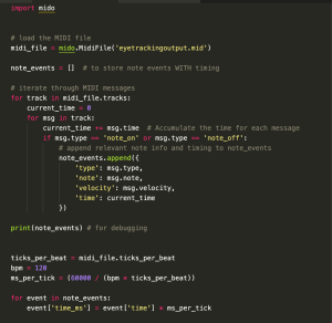
    • This week, as part of integration testing as well as addressing edge cases, I made sure to test on some MIDI files specifically created by Fiona’s MIDI generation code that our eyetracking system will use. Since we do not have eyetracking implemented yet, she has a temporary function that allows her to click notes on her UI (eventually, eye commands will take the place of this). She put the generated MIDI file into a sheet music converter and verified that the produced sheet music looks accurate. I loaded her MIDI file into my parsing code and was successfully able to match with what she intended to compose. Below is my terminal output. Bear in mind, this is a simple and short song with notes that have all equal lengths.
    • Next, I moved onto testing larger and more complicated songs. I decided to use sample MIDI files from a Github page:  https://github.com/urswilke/miditapyr/ 
    • This is where I’ve encountered issues. First,  I realised my code was outputting some zero-duration notes (which doesn’t make sense), but the list of pitches was accurate. I attempted to fix it and was able to be rid of zero-duration notes but now, every time a rest-note was encountered, 2-3 new phantom notes appeared as well.
      • I investigated potential causes related to the mido library’s use of relative timing (instead of each note possessing an absolute time value, it possesses the time since the previous note), which probably is still where the bug lies.
  • Research and troubleshooting on MIDI parsing code:
    • I explored additional resources to understand mido library limitations and potential solutions, including analyzing third-party code (Reddit, Github) and documentation from the mido developers on handling absolute vs. relative MIDI timing.
    • This may be an issue for Fiona and I to solve together. We realised that we both are still confused on mido’s nature of handling chords. It may be good to consolidate our understanding together.
    • I think there’s a possibility that even if my parsing code fails on sample third-party MIDI files, it may be still be perfectly suitable for our project. What’s important is that it’s compatible with the way Fiona generates MIDI files, and she might find a way to do it in a more intuitive manner than the person who generated the Github files.

For reference, I am attaching my code. The first version (produces accurate pitches but some zero-duration notes) is currently commented. The second version (produces unwanted phantom notes) is not commented. WordPress is not allowing me to attach the .py file for security reasons, so I’m attaching it as a PDF: current python midi parsing code

  • Hardware Preparation:
    • Set up initial hardware for solenoid testing, including connecting a single solenoid to a breadboard and verifying functionality.
    • Tested solenoid activation by inputting a square wave from function generator. We did observe expected behaviour, but encountered 1-2 unexpected actuations after disconnecting the power supply.
    • Verified that the MOSFET and flyback diode was installed correctly, ensuring protection against voltage spikes. Further investigation is underway to identify and prevent unintended post-power disconnection actuations. One idea I have is that a Zener diode may be needed additionally, to connect in series with the Schottky flyback.
    • Video of solenoid circuit successfully actuating: https://drive.google.com/file/d/1E0uiThGWiQmukMVjhNL5qg8HktBq021e/view?usp=sharing

Going forwards, I would really like to wrap up the MIDI parsing code by Monday or Tuesday, such that all edge cases (rest-notes and chords) are handled correctly and I am able to integrate/cross-verify with Fiona’s end. I will order an octave’s worth of solenoids asap. Once I wrap up MIDI parsing, I need to focus heavily on STM32 firmware code to have a bare-bones-functioning (hopefully, even more) hardware-end of the project by the interim demo on Nov. 18.

Shravya’s Status Report for 11/02/2024

This week:

  1. MIDI Parsing Code Development:
    • Built upon last week’s partial implementation of the MIDI parsing code. This week, I focused on completing the MIDI parsing functionality and structuring the code for readability and maintainability. In my last status report I said I want to have a bare-bones functioning MIDI-parsing feature this week and I think I have achieved that.
    • Utilized the mido Python library to process the MIDI file, extracting note-on events and their corresponding durations.
  2. Testing Framework Setup for Local Simulation:
    • Since the hardware components only got delivered yesterday, I set up a simulation environment to test the MIDI parsing logic without needing physical hardware.
    • Modified the Python code to print parsed note and duration data to the console, instead of transmitting over UART. This modification allows for verifying the output sequence and timing without hardware dependencies.
  3. Local Testing Execution:
    • Conducted initial local tests using some very simple sample MIDI files. Observed console output to confirm correct parsing of notes and durations.
    • Implemented timing simulation with time.sleep() to replicate the actual note durations, which helped in verifying the accuracy of timing based on MIDI note lengths.
    • Next week I need to work more on multiple test cases with more complex MIDI files to strengthen parsing capability under various conditions.
  4. STM 32 code which I have begun working on is designed to process MIDI commands received over UART and control solenoids accordingly. It involves use of STM32’s HAL library functions.
  5. Code Documentation and Clean-up:
    • Documented the code structure and added comments to each function, making it easier to understand and maintain.
    • Structured the parsing logic to handle only the necessary MIDI events (e.g., note-on events with non-zero velocity), improving code efficiency and readability.

Overall, this week had some significant progress in building the MIDI-controlled solenoid system. The next phase will focus on integrating the hardware components and refining the STM32’s control logic to create a robust, responsive system that accurately translates MIDI data into solenoid actuation. The hardware components got delivered a little later than expected (Friday, Nov 1st) but at least my efforts with testing MIDI-parsing functionality will allow us to proceed with more confidence when integrating the hardware.

Shravya’s status report for 10/26/2024

This week I worked on my ethics assignment, spent some time with my teammates processing the feedback we got from staff regarding our design report, worked on my MIDI to firmware conversion code, and devised some small-scale testing plans to ensure the components we ordered will work correctly.

Initial components testing

I am waiting for some more components (for the solenoid control circuitry) to arrive this week. Once they do, I will probably spend an evening running tests such as the following:


Test the Solenoid

  • Activation Test: Connect the solenoid directly to the power supply and confirm it activates within the specified current range.
  • Power Consumption: Measure the actual current draw and compare it with specifications.
  • Thermal Testing: Run the solenoid for an extended period and monitor for any significant heating to ensure it can sustain operation without overheating.
  • Measure any delays in reaction time


Test flyback diode reliability

  • With the diode installed, use an oscilloscope to measure voltage at the MOSFET drain (or across the solenoid) when the circuit is deactivated. Take note of the voltage spike when switching off power to the solenoid and note how effectively the diode suppresses back EMF.
  • One piece of feedback I received from the design report on a section I wrote was that the equation I used for energy dissipation wasn’t extremely necessary to include and rather I should have included a Vspike equation to quantify the back-voltage. I agree with this feedback, and when I run physical tests I will take note of the Vspike and how that may affect other quantities; I will include this in the final report.


Test the MOSFET

  • Switching Test: Use a low-frequency signal from the function generator to control the MOSFET, checking that it switches the solenoid on and off without issues.
  • Thermal Stability: Measure temperature over a few switching cycles. Confirm that the MOSFET consistently stays within a safe temperature range


My progress on MIDI to firmware conversion code

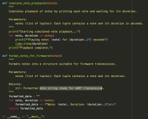
I have gotten a grasp on how to parse MIDI with Python’s Mido library to extract note events. I am also able to generate C-compatible data to output an array of structs in a C header file. I will keep fine-tuning this as necessary and this week I will also work on writing the final “integration” code, as in, using the C array to send commands from the STM32 to actuate the solenoids. I have attached a screenshot of some of my code.

I am on schedule. I hope to have the bulk of my components testing finished this week as well as a bare-bones functioning midi-to-firmware conversion code (I want it to function save for any edge cases, minor bugs, etc). I will also be working more on the ethics assignment this week after having pod discussion in lecture.

Shravya’s Status Report for 10/20/2024

Week before fall break

All of my time this week was focused on completing the design report. We had meetings on 4 of the days and there was plenty of individual work on top of that.

Fall break

Over fall break, I was extremely occupied with a project and homework for my 18421 class.

Next week

I am waiting on a preliminary order of solenoid circuit components, and as soon as they arrive, I can expect to spend a few hours testing them out with a power supply and oscilloscope. Testing them out physically will prove more fruitful than Cadence simulations, I’ve come to realise- Cadence is too ideal, and it takes time for me to introduce parasitics to make components behave more realistic. It’s simply not a good use of my time when I could be working with the real components, and Joshna and Professor Bain agreed with me on this in our most recent meeting.

This week I will also start writing code for MIDI to firmware conversion using the python MIDO library.

I have indeed fallen slightly behind schedule but I am confident I can get back up to speed this week. Besides, we had allocated about 2 weeks of slack time at the end of the semester in our Gantt chart, some of which will help me right now.

Shravya’s Status Report for 10/05/2024

This week

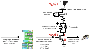
As a recap of what I touched on last week already: An STM32’s GPIO pins have a 3.3V output, but a push-pull solenoid may need 12V. Therefore, we will need to have the STM32’s GPIO pin output of 3.3V function as an enable line to control whether a solenoid is on/off, rather than serve the purpose of a supply voltage. We can feed the 3.3V into the gate of a MOSFET to do this.

We had always agreed on the circuit diagram. However, Peter assumed we would use a PMOS, and I assumed we would use an NMOS. An update from this week is that we resolved this confusion. In our circuit diagrams we had placed the MOSFET between the solenoid and ground. In this case, it is correct to use an NMOS as an NMOS gate-source voltage being higher than the threshold voltage enables the device, and the NMOS acts as a low-side switch since it completes the rest of the circuit’s connection to ground. A PMOS would work in a similar way as a high-side switch if it was placed immediately below the power supply, because a PMOS turns on when the gate-source voltage is more negative than the threshold voltage (Vth). It was easier to keep the circuit diagram drawing we already did (with the MOSFET connecting the solenoid to ground) as is, and we simply made sure the MOSFET icon was an NMOS not a PMOS.

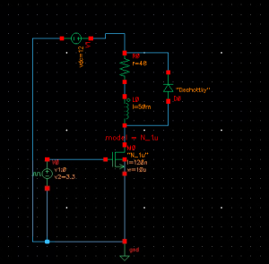
According to the schedule, this week I was supposed to run Cadence simulations regarding the circuit, and so I did.

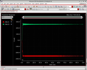
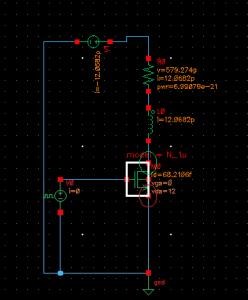
I had to conduct (refer to plots):

  1. Transient Analysis/time-domain simulation:
  • Verify the voltage across the solenoid is 12V when the NMOS is fully on.
  • When the NMOS turns off, ensure the flyback diode handles the transient current spike from the solenoid without issues.

2. DC operating point analysis:

  • Apply a 3.3V GPIO signal to the NMOS gate, verify it turns on and off correctly. Measure the current through the solenoid (it should reach 250mA).
This was the intended circuit. However, ADEL cannot generate any netlists/run any simulations as there is no built-in model card for diodes. When I tried to add in some model cards I downloaded online, I got errors + troubleshooted, but ultimately had to take out the diode.


The transient analysis shows that, as expected, 250 mA of current pass through solenoid and that the switching behaviour is quite instantaneous.
Annoted with DC operating points

On an aside, I am curious to understand why, fundamentally, there is a transient current spike when solenoids turn off. Not that this is too important for the project, but I want to know more for my own general ECE knowledge.


Next week

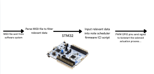
I will start familiarising myself with Python’s MIDO library to parse + convert MIDI file data into a bit-packet format that is suitable to feed into the STM32 for solenoid actuation.

Shravya’s Status Report for 09/28/24

This week, my primary focus was on preparing for the design review presentation. As part of this effort, I created the hardware system block diagram, which outlines how the different components of our project will interact with one another- find attached below. Additionally, I worked on designing the electrical circuit (visible in the second image) for the solenoid control system. This design includes obvious components, but I’ve realized that integrating MOSFET amplifiers is critical to making the circuit function properly. This is because the signal output by the GPIO pin is 3.3V which is too low of a voltage to input into solenoids + activate them. Hence, a common source NMOS configuration can amplify.

Unfortunately, I fell slightly behind schedule this week due to two midterms and the preparation required for the design presentation. I wasn’t able to begin running the Cadence simulations, as planned, but I will prioritize this first thing next week. To catch up, I’ve already blocked out additional time to focus on running these simulations and ensure the electrical circuit I designed operates as expected.

Next week, I plan to finalize and run the simulations in Cadence, ensuring the circuit is functioning as intended. Additionally, I will focus on learning more about how Pulse Width Modulation (PWM) works and how it can be integrated into our system to improve power efficiency. I’ll be working with Peter to begin testing how one solenoid works.

Shravya’s Status Report for 9/21

At the beginning of this week, I helped polish the Proposal Presentation slides. Specifically, I worked on defining the technical challenges (both hardware and software), specifying testing methodology + performance metrics for different parameters (accuracy, eye-tracking detection latency, solenoid latency, and power consumption) and contributed to shaping the overall structure of the Gantt chart. I also participated in preparing Fiona for the oral presentation; Peter and I spent about 2 hours to help her practice her public speaking skills as well as refine her script after seeing the first round of presentations on Monday.

I began research on the power management system for the solenoids, which is critical for ensuring stable and efficient operation. Since solenoids require precise voltage and current control, I’ve been exploring different power management circuits and components.

In order to integrate Low Dropout Regulators (LDOs) -a type of linear voltage regulator- into our solenoid power management system, I have been studying the LM7805 in particular. Our case is such that the input voltage is only marginally higher than the intended output voltage, which is a perfect fit for LDOs. This is essential to guarantee that the solenoids receive a steady, uniform voltage; variations may cause irregular key presses or deterioration of the solenoids over time.

I’ve also decided that it would be beneficial to include decoupling capacitors in our custom PCB to stabilize the voltage supply and prevent noise that could affect solenoid performance. This is a very standard practice for PCB design.

Moving forward, I need to narrow down the specific components for the solenoid control circuit and run initial simulations to ensure everything will function as expected. These simulations can be done in Cadence Virtuoso ADE. I can start by running transient analysis to simulate how the voltage and current evolve over time, especially as the solenoid is actuated. It’s important I simulate a single solenoid actively pressing as well MULTIPLE solenoids simultaneously pressing, as we are going to be implementing chord functionality (up to three simultaneous notes).

The waveform viewer will also be useful to check for any instability (e.g., fluctuating voltage or high power dissipation). For my simulation data to be useful, I need to first know which particular solenoid components we plan to order (I need to make sure the current and output voltage from regulator don’t exceed solenoid’s maximum ratings). Thus, I suppose one dependency I have here is for Peter to finalise some preliminary component selections as he is the one in charge of selecting which solenoids we will use.

We will also be working on the design review presentation this upcoming week.

I am on schedule at the moment, but I’m aware that this is the point in the semester that the project starts to get busy as we are going to begin with the true, hands-on engineering.