This week in a meeting with my professor and TA we explored a technical challenge in our previous design, which was the question of how to power a movable rechargeable robot. We started with two solutions: one was to use wires to power the robots, however the tangling and resistance of the wires could cause a number of complications; the other was to add batteries to each of the robots, however after doing some research we realized that it would be difficult to charge the robots by homing them in place as the electrodes are too small and would place a huge demand on the robot’s controls and would be difficult to control. too large an electrode would pose problems such as circuit safety.
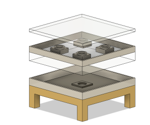
After several iterations this week, we finally decided to use a completely new design. We used the Gantry system, however, in order to achieve the effect of charging multiple devices at the same time, we came up with the innovative idea of using magnets on the end of the Gantry to move the charging pads across a layer of acrylic. This design is stable and efficient and allows for the charging of multiple devices.
After finalizing the design, I completed the mechanical design for the second version. This version focused more on the internal principles and concepts than the previous design, using real dimensions and an aluminum frame. This also meant that our design was being further refined. However, our Gantry system does not have the ability to purchase a frame directly due to its size, so we are still researching and discussing the design of this system. However the overall design is still very clear, and I have set deadlines for the complete overall design and hardware purchases that need to be made before fall break to ensure that our plans can continue to develop as we expect.


