Zina’s Status Report for 4/20/24
Since my last status report, I made a lot of progress on my portion of the project, but also encountered some unexpected challenges. I tested out the PCBs that we received by hooking up some LEDs to a breadboarded circuit and ran the Arduino code that I wrote to control the LED driver chip. I discovered a wiring issue related to the reference resistor R_IREF which sets the constant-current output that is delivered to each output of the LED driver. I initially thought that this resistor was supposed to be connected between the IREF and V_CC pins, but this connection to V_CC actually happens internally in the chip. Instead, the resistor is supposed to be between IREF and ground. Additionally, I thought that the LEDs were supposed to be connected to the chip’s outputs at their anode with the cathode going to ground, but it turns out that the chip is actually a current-sink rather than a source, so the LEDs needed to be flipped around with their cathodes at the chip outputs and their anodes tied to a voltage source. I redid the PCB layout to fix these problems and ordered the updated boards so that the circuit for our final demonstration will be completely integrated, rather than having parts of it wired up on the breadboard. This was my first time designing a circuit from scratch and laying out a corresponding PCB, so I definitely learned a lot throughout the process. I should have read the TLC5928 LED driver chip’s specification document more carefully so that I would have known how to connect all of the pins properly before ordering PCBs. Despite some misunderstandings about the component I chose, the PCBs do operate exactly as I designed them to, with all of the pads and tracks connecting the nodes I originally intended to connect, so I am proud of the fact that I taught myself how to design a PCB and did it right on my first attempt, albeit for a circuit that was wrong to begin with.
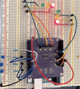
Here is what my breadboarded PCB test circuit looked like, which we will use as a backup for the demo in case the new PCBs don’t arrive in time or have unexpected issues:
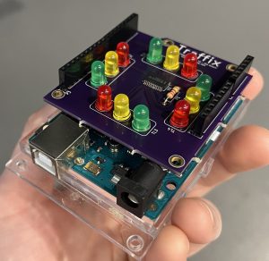
And here is a picture of what the final demo is intended to look like, with the fully assembled PCB stacked on top of the Arduino:
Last week, Ankita and I also got the RPi -> Arduino serial communication working, but I have not yet set up the Arduino to actually display the proper light pattern based on the current state information that is received. My plan for the next week is to get that working and then put together the new PCBs when they arrive so that we can make sure all of the pieces are working together for our final demo next Friday.