Carson’s Status Report for April 27, 2024

Progress

This week we put together the wearable version of the watch, including support for SD card point logging, map loading, and time display, and tested it on a walk through Schenley. The test went very well, though the GPS sample rate was much too high and there were a few occasions where the GPS returned a very incorrect sample point.

However, several things notably went very right:

  • The map was seamlessly loaded from the SD card as we walked, keeping our location at the center of the screen and showing nearby paths
  • The logging of the path worked, and we were able to plot the points later.
  • The watch felt fairly comfortable and stayed on the wrist even while trying to step carefully over mud, jump across rocks on a stream, etc.
  • The battery was charged from the solar panel and appeared to remain constant while in the sun.

Unfortunately, that was the only task I could manage this week due to traveling for another event.

Pacing

Most of the main functionality is worked out; though we have a lot of things to do related to the documentation (video, poster, etc).

Planning

Next week we will finish the poster and the video.

Carson’s Status Report for April 20th, 2024

Progress

This week, I got numbers on the energy output of the motor, and we assembled the final watch.

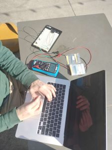
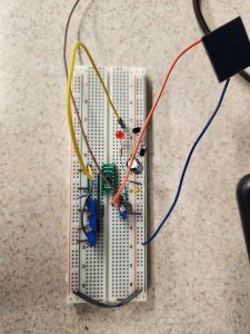
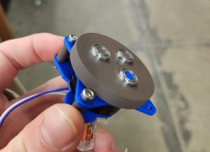
After many difficulties trying to get the tolerances correct and having to adjust the gear ratio, I finally was able to attach the motor to my arm and collect data on its energy output. The data was very noisy due to the imprecision of my own motion, and I could only record for short periods of time due to the fact that I could not find the set of ball bearings I needed to keep the two halves of the gearbox in line. However, when the parts were aligned correctly, it swung very well and yielded 1-2mW of power output at what felt like a running pace. This is comparable to the power output of the paper we were referencing; the 50% loss in efficiency is likely due to problems with my mechanical design. With some refinement, this means the motor could be a viable energy source for the watch. However, the main issue is size; the current gearbox is the same as the size of the entire watch body, and to get it smaller would require integrating the rotor, stator, and gears into a single custom assembly. This could be interesting for further research, but for now it just isn’t viable.

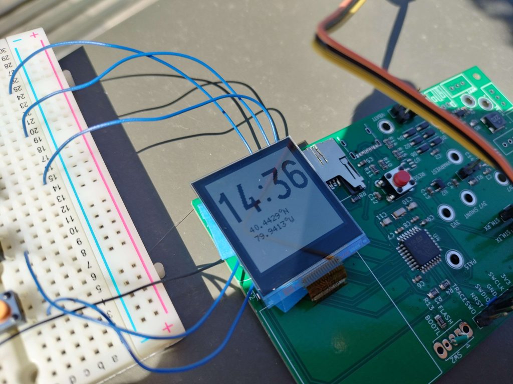
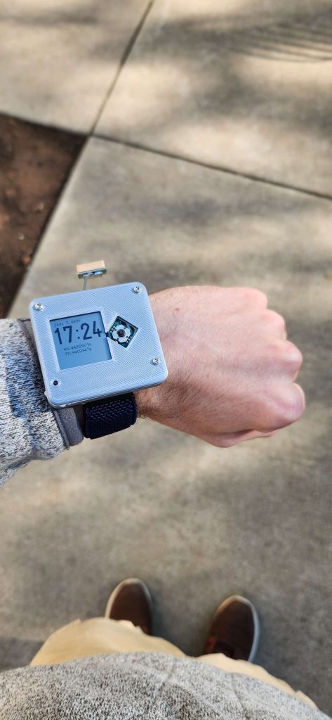
Just yesterday we were able to assemble the final revision of the PCB. I did some modifications to the case design to make the PCB fit, assembled a small “debug header” with pogo pins to program the new board, and also ported over our code to work with the new pin layout. Amazingly, everything worked:

Learning

Over the course of this project, I had to learn many new things: low power circuit design, gear manufacturing, GPS protocols, SD card interfaces, debugger setup…

Many of the “formal” aspects of implementing these ideas came from reading research papers and datasheets—in particular, this is how I would get equations, design parameters, and circuit layouts, for determining at a high level how I should accomplish a task. Then, inevitably, while trying to do most tasks I would find that the high-level overview leaves out several steps, or doesn’t quite work in practice. This then usually lead me to Google, where I pieced together forum and blog posts from people with vaguely similar problems  to see how I could solve my own. And, finally, I would sanity check my ideas with people I knew had knowledge–first my team members, and then my friends (in particular, it was quite hard to get mechanical engineering advice anywhere other than in-person).

Pacing

The only remaining item is the firmware, which is a little bit behind where I’d like it to be but is very much doable now that we have two sets of real hardware to test with.

Planning

Next week I will:

  • Implement actual menu navigation
  • Find a way to display the path the user has taken on the map
  • Determine if there’s an easier way to use the USB bootloader on our final PCB

Carson’s Status Report for April 6th, 2024

Progress

This week I made the system fully energy-independent, able to power itself from its own battery. This involved a lot of tuning of the resistor values for the ADP5090 boost converter, to avoid accidentally setting the LiPo battery on fire. I also conducted some preliminary tests on how much energy we could harvest, and the results vastly exceeded my expectations. With a partially-overcast sky, the solar panel yielded about 0.6mA-1mA of current. This is already very impressive, consdering our quiescent draw of only 0.3mA. In direct sunlight, I observed up to 15mA of current from the panel, easily enough to charge the battery even with all the components active. This far exceeds any expectations we had of how much energy we could obtain, and gives us very strong evidence that we should use the panel.

Pacing

With most things working, we now just need to integrate the components into the firmware. This is taking longer than expected, but given that I have now completed my most time-intensive outstanding task (Robobuggy) I should much more time available to focus on finishing that up.

Planning

  • Confirm that the motor is not nearly as viable as the solar panel
  • Fix loading map tiles from the SD card

Carson’s Status Report for March 30th, 2024

Progress

This week I was very busy with preparing Robobuggy for rolls, so I didn’t have much time to spend on this project. I mostly made some tweaks to the map and worked on updating the HAL (hardware abstraction layer) library we use to a later version so that it was compatible with the SD card library, so that we can start working on adding map tiles.

Pacing

We are somewhat behind on overall progress, but we have a really strong set of features for the demo. Fortunately we can have some asynchronous tasks (i.e. having the next PCB be ordered while we work further on firmware).

Planning

Next week we will do final preparations for interim demo (real energy harvesting numbers, demo firmware, etc).

Carson’s Status Report for March 23rd, 2024

Progress

This week, we assembled and tested our prototype PCB. I did most of the testing to confirm that the new board worked, including determining how to use a Raspberry Pi debug probe to flash code to the new board as well as rewriting the code to work with the changed pin assignments.

Some notable things I discovered while testing included the SD card connector being inconveniently backwards, the display pins being inverted (which we fixed by rotating the display around), and there was a noticeably longer time to get a GPS fix than there was using the breakout.

Pacing

The fact that the PCB functions is very good news; though this deviated from the original plan we now can start measuring energy consumption and checking for the accuracy of the GPS fix. I still have not gotten energy harvesting measurements, but now that we have a more concrete setup it should be easier.

Planning

Next week, I will:

  • Finally determine the energy harvesting scheme we will use
  • Start design of the final PCB

Carson’s Status Report for March 16th, 2024

Progress

This week I helped write some of the asynchronous backend code for the firmware (along with Gary) and did some preliminary energy harvesting tests with the solar panel. For the energy harvesting, I did some measurements of the solar panel to see if it would be viable. We purchased a solar panel small enough to fit on the band of the watch (23mm x 25mm) and tested it outside with a variety of resistances to find the optimal range for power output. Unfortunately, the weather was changing too quickly to do a complete test, but all measurements showed at least 5mW of power output, and one showed above 15mW. These numbers are incredibly high, and give us a considerable margin for losses should we decide to use a panel. To further test this idea, I built the ADP5090-based boost converter circuit and used it to power an LED. Simply pointing my phone’s flashlight at the solar panel from ~10cm away was enough to power the LED intermittently. This was very impressive. Again, I will need to do more thorough tests in the future, but this is a promising power source.

Pacing

This week I would’ve liked to get some more quantitative measurements of more sources, but I was very busy with other obligations. Next week I don’t have much to be working on, so I should be able to catch up on the testing.

Planning

Next week, I will:

  • Finish the measurements of the motor system
  • Finish the measurements of the piezoelectric system
  • Determine how efficiently the ADP5090 can charge the battery

Carson’s Status Update for March 9th, 2024

Progress

This week, I finalized the layout for the prototype version of our PCB, and made a more functional prototype of the gearbox for the kinetic energy harvesting. The gearbox does spin and has minimal friction. However, the gear ratio is too high, so too much force is required to get the motor to start spinning. This means that even after attaching external weights, the motor would not spin when swung. Fortunately, the design is parametric, so I can experiment with less aggressive gear ratios, which will make it easier for the weight to turn the motor. Just spinning it a quarter-rotation by hand fairly slowly, I could already get 2 volts, so there is plenty of margin to make the gear ratio lower. We only need about 600mV for the energy harvesting to work.

Pacing

This PCB should have been ordered over Spring Break, but unfortunately there were several difficulties with part selection, having to create custom symbols and footprints, and having to learn how to do impedance control on a trace. Fortunately we can still do our testing on a breadboard; I will focus on getting efficiency from the energy harvesting while the board is being manufactured.

Planning

Next week, I need to:

  • Get a gearbox that spins under its own weight
  • Measure performance numbers for the energy harvesting strategies

Carson’s Status Update for February 24th, 2024

Progress

My primary accomplishment this week was designing the gearbox that will be used for the motor-based energy harvesting scheme. The gear ratio and general structure was based on the design by Cai, Liao, et. al, but I had to determine the exact dimensions, optimal gear profile, mounting strategy, etc. myself.

I printed using the “Extra Fine” slicer settings and standard print speed on the Robotics Club Bambu X1 Carbon printer in PLA. The result worked astonishingly well, spinning smoothly enough to keep going off of inertia alone for about a second. Even with the small amount of weight provided by three M6 nuts and minimal balancing, the gearbox would spin in my hand as I swung my arm. We were unfortunately unable to attach the motor for real power measurements, as we discovered that we needed M1.6 size screws, but even so this is very promising.

Pacing

Working on the gearbox put me somewhat behind on the PCB design; I will need to work on that some more next week. Fortunately, the gearbox testing is doing much better than expected, so I should be able to catch up.

Planning

Next week, I will:

  • Attach the gearbox to the motor and get real numbers on power output
  • Do the layout for the PCB so it can be ordered over Spring Break

Carson’s Status Update for February 17th, 2024

Progress

My primary accomplishment this week was in making a first (very rough!) draft of the board schematic. It is missing a few connectors and features useful for testing (jumpers, test points, spare pins, etc.), but it’s very useful for checking if there’s any major design details we’ve overlooked. Thankfully, there weren’t any.

Pacing

I am roughly on pace right now.

Planning

By next week, our components should have arrived. This means I can start testing the energy harvesting setup and experiment to find the optimal setup, and then get real numbers on how much power we can source.

Carson Swoveland’s Status Report for February 10th, 2024

Progress

This week I did literature review for the energy harvesting part of the project. I made a number of interesting notes from these papers, with the most important ones being:

Piezoelectric energy harvester impedance matching using a piezoelectric transformer

Though sourcing a piezoelectric transformer is infeasible, this paper did give some insights on some of the challenges to getting optimal power transfer from piezoelectric elements. The major concern was the fact that at low frequencies (the typical frequencies of human motion), the impedance of a piezoelectric element is largely capacitive. The inductance required to match this capacitance is typically infeasibly large to achieve on a wearable device, so instead mostly resistive matching is done.

A Coaxial Wrist-Worn Energy Harvester for Self-Powered Internet of Things Sensors

This paper proposed the use of a motor and weight for energy harvesting. Surprisingly, it achieved power generation of ~3mW average at a normal walking pace, which far exceeds the capability of the state of the art in piezoelectric generators (as far as I could find). Originally we discarded the idea of using a motor for energy harvesting due to mechanical complexity, but after some discussion we realized that we may be able to use a standard gimbal motor and 3D print a planetary gearbox for the top. We will be experimenting with both methods to see which one is more effective.

Low-Power Design of a Self-powered Piezoelectric Energy Harvesting System With Maximum Power Point Tracking

This paper presented the most thorough design for the voltage regulation and conversion that I’ve found so far,  and goes into great detail on the design considerations for implementing a circuit for low-power use. I expect that my design will be primarily based on the techniques discussed here.

Pacing

I am roughly on pace right now.

Planning

Next week, I will start the more detailed design of the energy harvesting circuit, and do some hands-on testing of piezoelectric elements I have laying around. My goals are:

  • Create preliminary design for Boost/Buck Impedance Matching
  • Test Boost/Buck Impedance Matching on Breadboard