
The two main things I’ve done since the last progress report are related to the PCB, case assembly, and testing.
First, I remembered that I have IDEATE access so I went to the physical computing lab to look at what they had. Happily, they have the fast-switching Zener diodes that we need, so we don’t need to order those anymore. They also have a variety of op-amps (which we thought were needed at the time) and Polulu boost converters so we don’t need to order any of those anymore, and I also took some buttons and switches. Then I also went to the PCB lab to count out the SMD resistors and capacitors to make sure we have enough of all our values. I labeled each strip since there’s no markings on the components themselves.
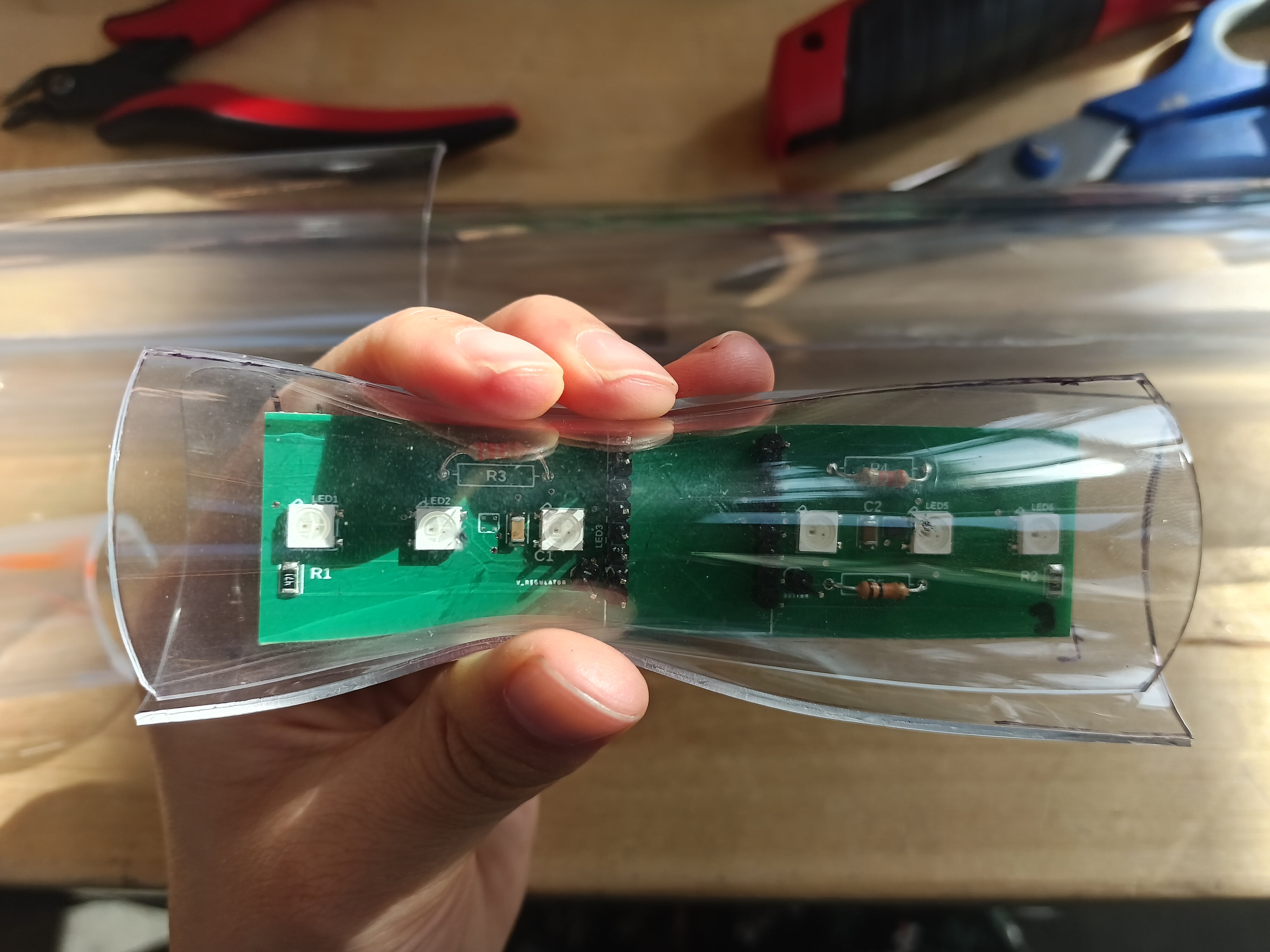
As a side quest, I also noticed that some of the header pin connections weren’t adequate (since the holes were still visible), so that made me wonder if that’s the reason the lights don’t work for all the boards. Especially since the lights are big enough and the soldering pads are far enough away that I can clearly see that SMD solder connections shouldn’t be the issue. After touching up the connections, we now have all the board’s lights working properly! Woohoo! That means the success of the boards only depends on mics, so by redoing the calculations, we’d need about 10 boards to be safe. Turns out the minimum number we can order is 15 so this will be fine (we bought enough Neopixels for about 28 boards so this will be fine ish, even with 2 designs which would be 30 boards total). I also took this opportunity to demonstrate how to solder to Katherine so she could try different resistor values for the mics (even electrical tape had a slightly sus connection, so soldering was necessary to properly test).
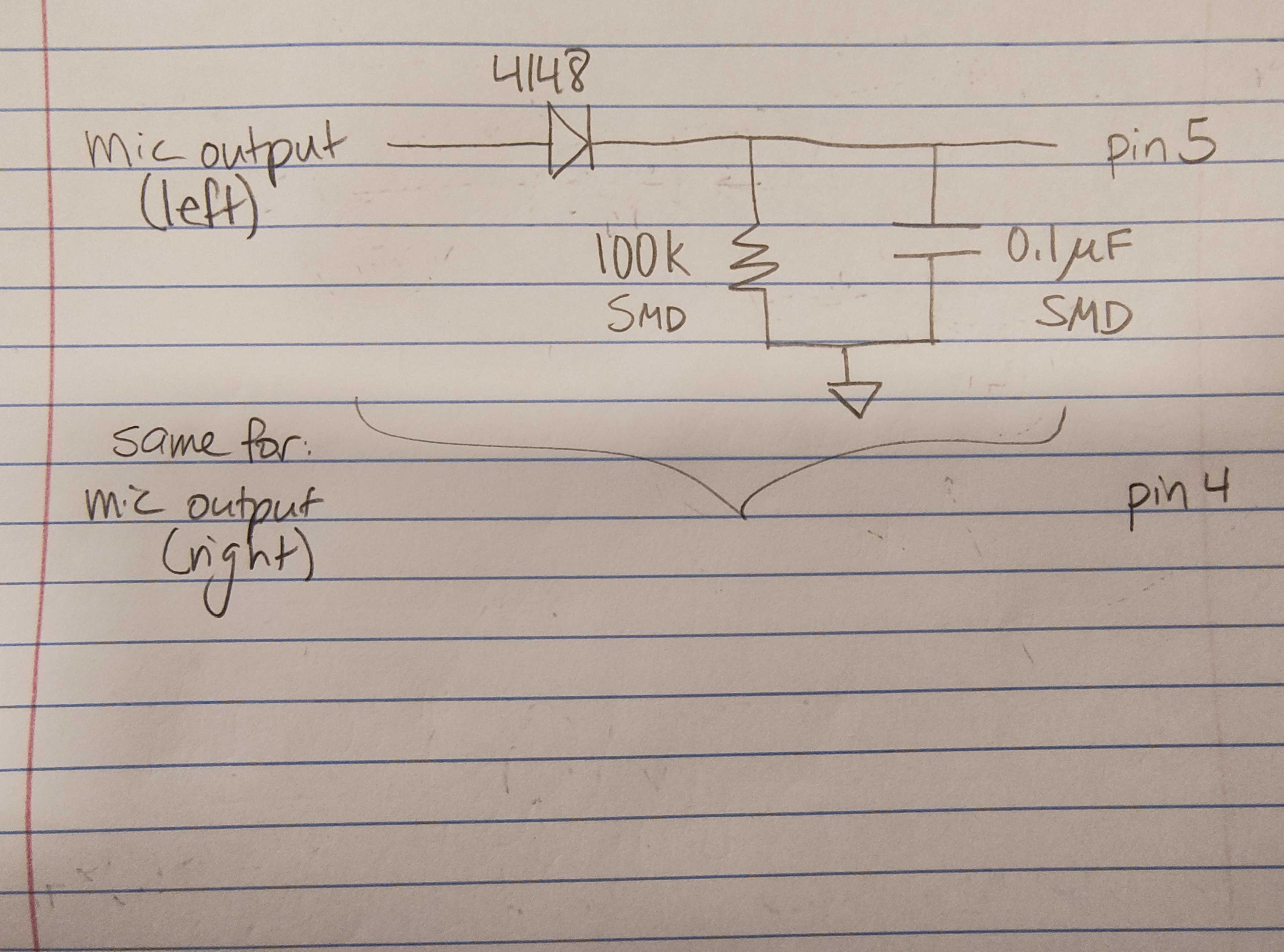
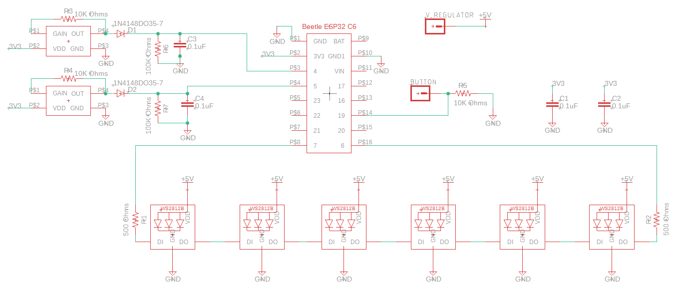
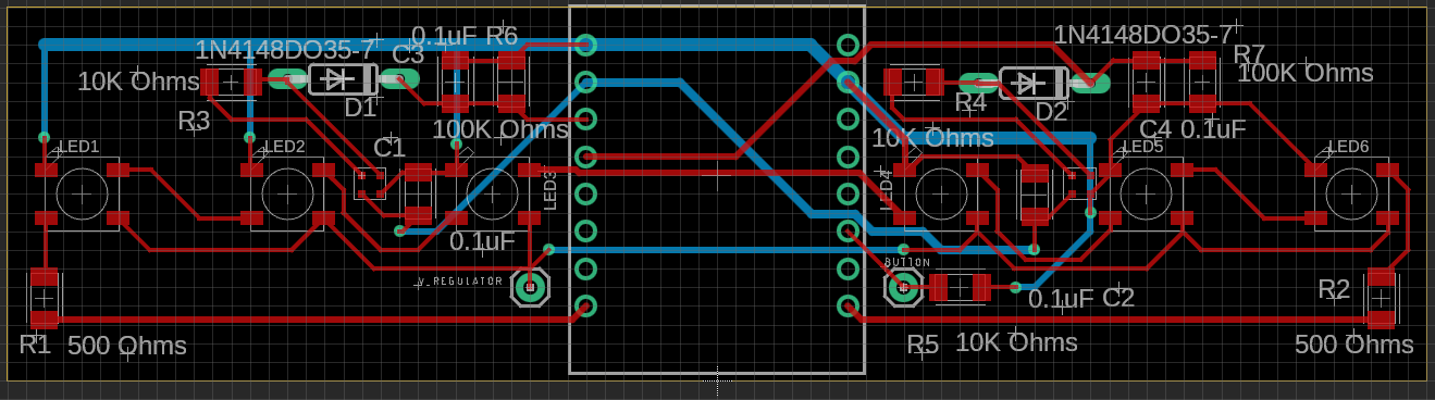
Next was redesigning the PCB to include the peak detector. For a while, we were debating whether we needed the op-amp. I preferred having as few components as possible since we were running low on space and it was going to be difficult to route things around such a large object. Prof Fedder also drew a simpler diagram where we only needed the “top half” of the peak detector, since we didn’t really care about enveloping the bottom-half of the signal, which further reduced the number of components in the original diagram by half. After Katherine did some simulations in Lspice, she confirmed that we don’t need the op-amp, thank goodness! That made my life easier. What didn’t make my life easier though, was Fusion 360 being weirdly different since the last time I designed it. For some reason, some components just didn’t snap to the same place in the grid as they did in the previous design, even though the grid granularity and components were the same. This was solved somewhat by rearranging the component order and then putting them back, or just sucking it up and saying “this slight difference shouldn’t affect the functionality” and moving on. Katherine did some calculations for the trace width resistance and ordered PCBs.
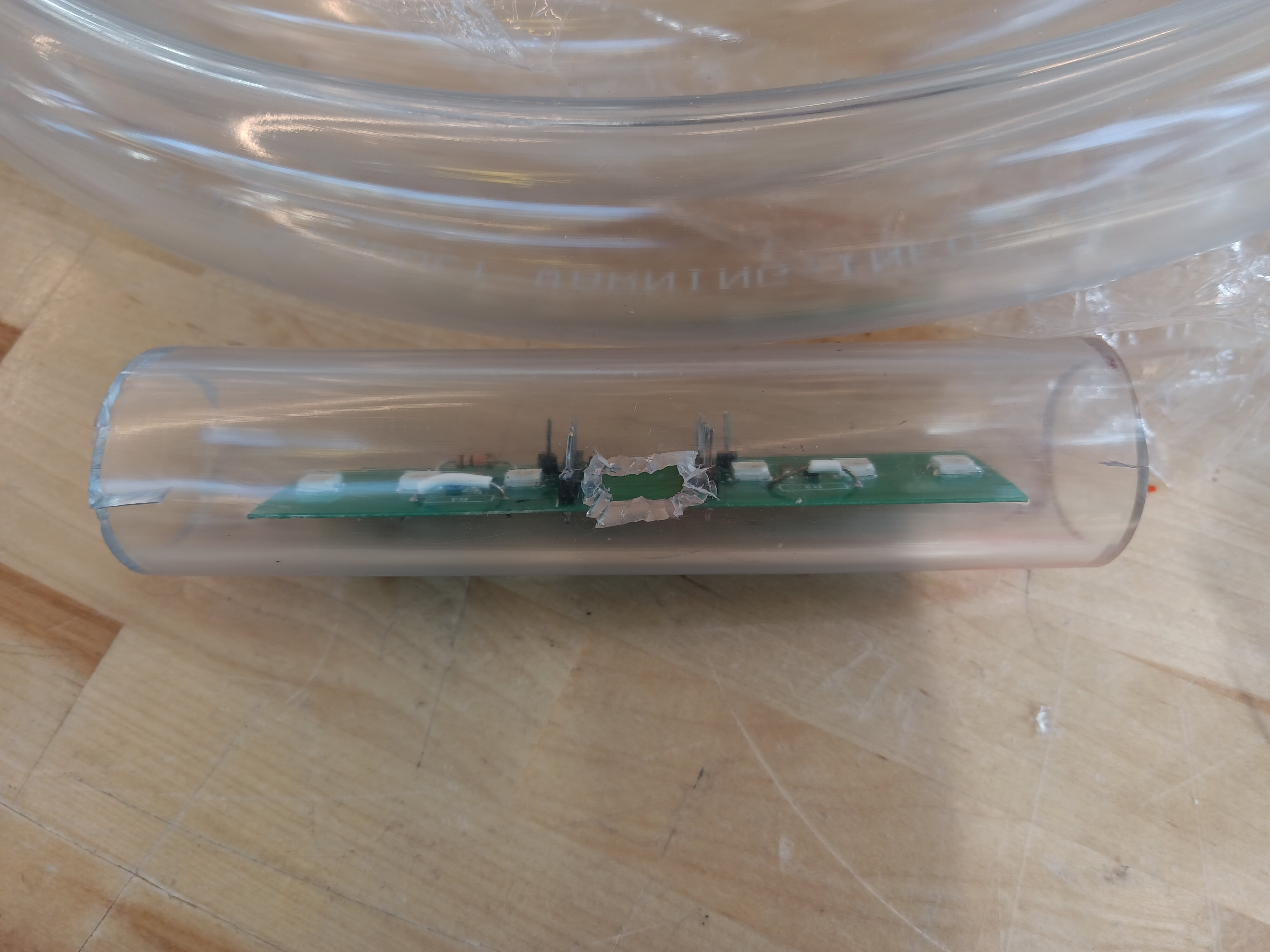
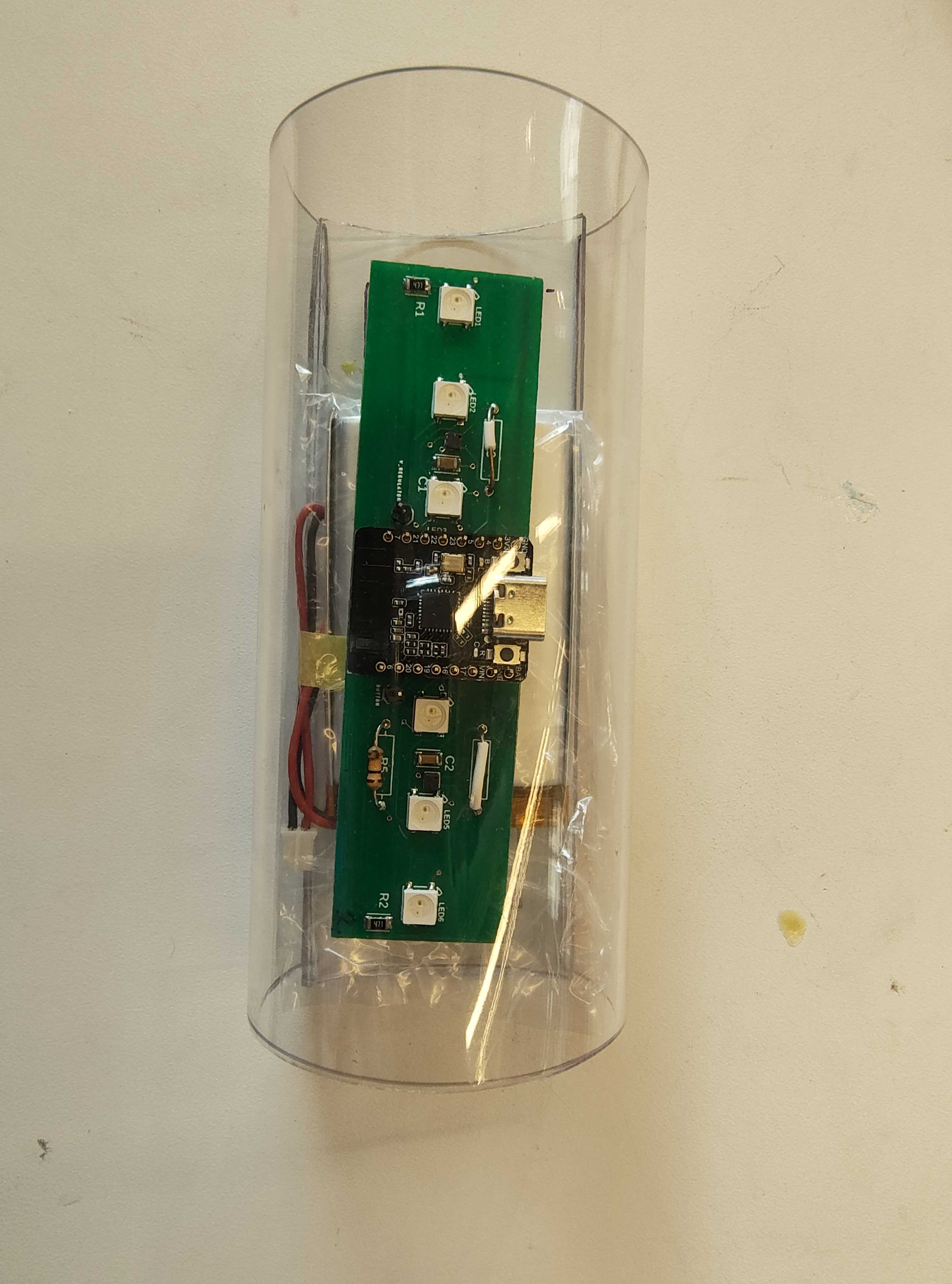
Cutting the plastic for the casing was also such a big pain! The tubing was decently easy to slice along the open edge, but the knife (and all other pointy objects I could find) were all not sharp/strong enough to puncture the tubing for cutting holes. I tried drilling to make the hole bigger, but the drill bit ends aren’t sharp enough to do much 🙁but it made the hole slightly larger so I could try fitting a small wire cutter in there to widen the hole. It took so long, and the hole ended up looking very jagged. Later, I realized that the battery couldn’t fit through the opening, even when squishing the pipe, and especially not if you need to add a PCB on top of that. So we’re not going to be using the tubing anymore.
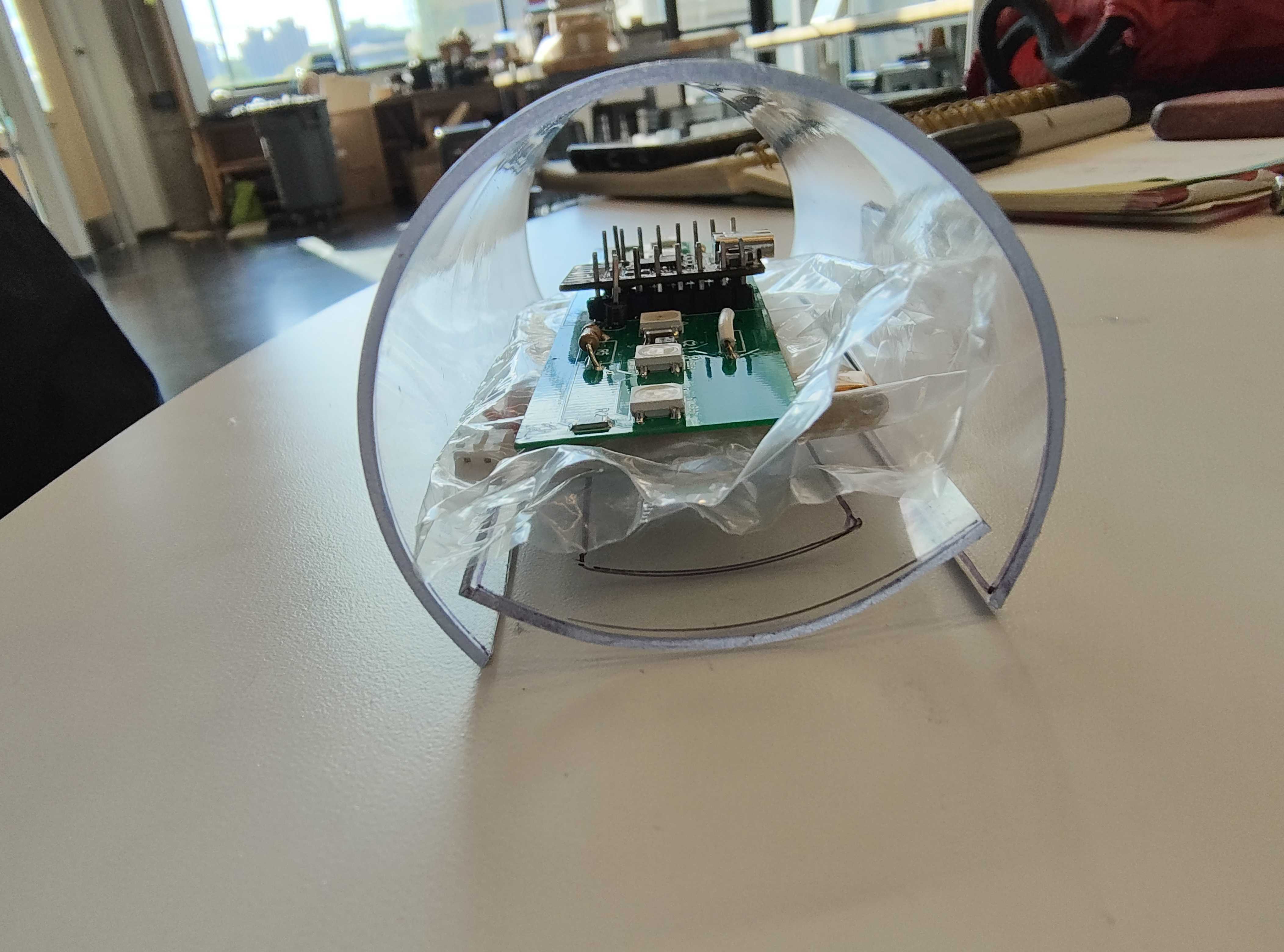
The back-up option was the rectangular plastic wrap, which we’d need to measure and cut and glue together again. This is more work than being given a tube, but it gives more customization options (and the plastic is also much thinner). It has the same problem as the tubing where it’s pretty puncture-proof (this is pretty good for durability, but it’s a pain when we’re trying to make holes), but a helpful Techspark person showed how to use the hole-puncher, so we were able to make some holes where the mics would be. I also tried the method of just gluing the edges of the top and bottom pieces of the plastic together, and testing the durability from bending. It starts off ok, but it takes a lot of glue to seal it well, and over time the glue cracks and the edges start opening.
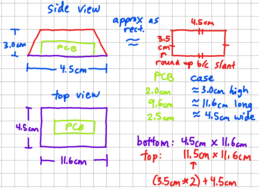
So for the next iteration I tried overlapping more surface area (thus, making the top piece of the casing much larger than the bottom piece). This time, I calculated how much I’d need for each piece instead of guesstimating. It’s hard to guess exactly how much I need because there are some variables that are hard to measure, such as the curve of the top piece. However, I think the sizing is all right because the height of the bracelet can be adjusted based on how much is overlapped with the bottom piece.
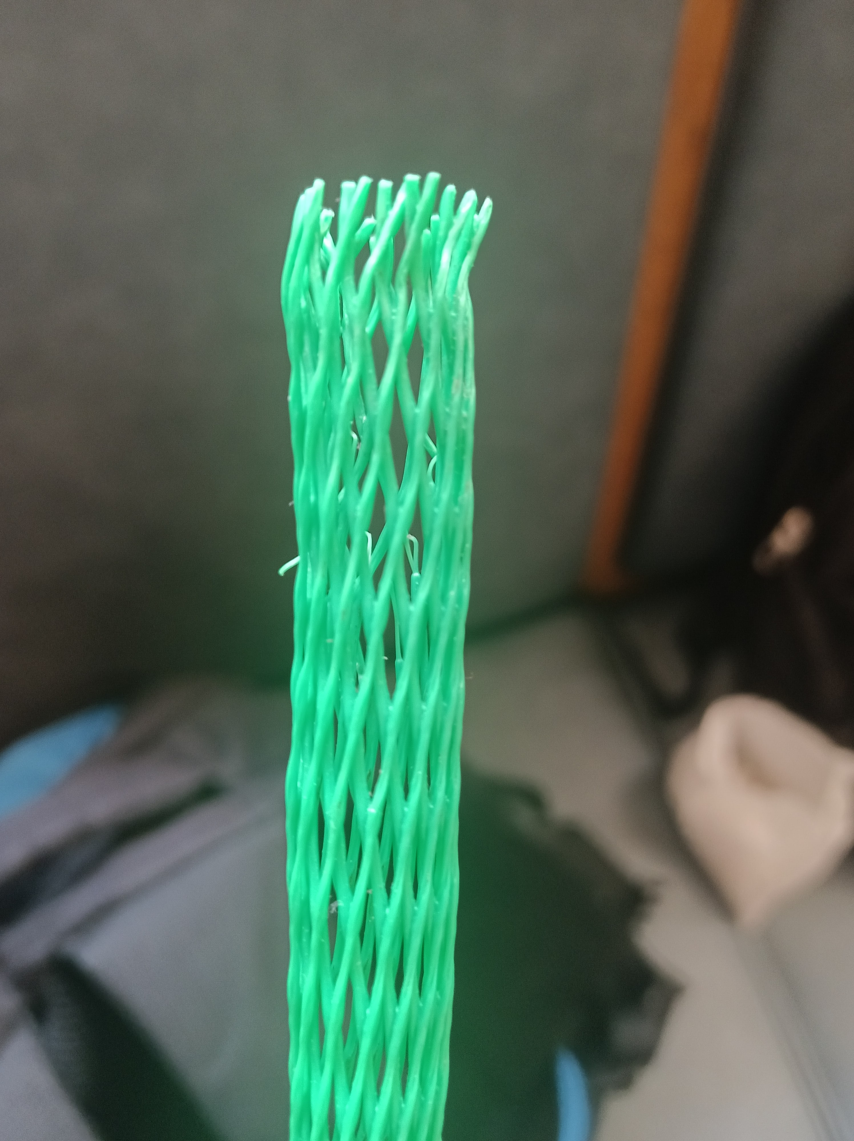
Prof Fedder also suggested that we need some netting to help protect the mics, so I found this plastic netting that we could use.
Originally, we planned to be done integrating (including the case) and onto testing by now, but of course that hasn’t happened. It’s hard to know if the casing design I have now will be greatly affected by having a flexible board instead, but I’ve discovered so many roadbumps in creating the casing that I think it’s important to keep going through the building process, even if it needs to be with a hard PCB. I aim to have a case finished by Wednesday (as in, the case is glued together, has the correct number of holes, and fits the battery and PCB with some room to spare). If the flex PCB arrives early enough, perhaps I will have time to test the fit and make adjustments before the next status report as well. I also plan to assemble the PCB with Lucy like last time, and also try to debug the button press.
Throughout this process, the way I’ve learned new things is through a few methods. Mainly, I try searching for tutorials (ex: on YouTube for PCB design like creating library components), and reading forums for how people have solved similar problems). In addition, I think an important method is knowing who’s an expert and consulting them for questions. The obvious one is our Prof and TA, but this also includes classmates (who are working on similar projects), and Techspark people (since they know what specialized tools are available and how to use them).