This week, I mostly worked on mic-related stuff, but also tried out the casing assembly.
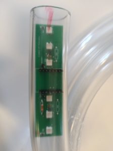
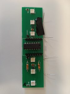
For the casing, I gently placed the board into the tube to check the fit, which it did.

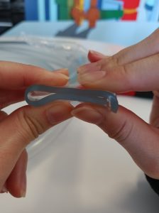
The tube is easily compressed, so even if the board is flexible, there should be enough room such that it won’t get caught on the walls from friction and buckle. If that doesn’t work, I still have the option of cutting some notches in the tube to expand it even more (probably needed some holes for the mics to work well too). For the ends, I think I can get away with not needing to laser cut acrylic stoppers and instead just press them into a line with enough hot glue and/or tying them down with the thread. The folding doesn’t quite close all the way because of the curve, so I cut a notch into the side to help it meet. You can see the pictures for a comparison.

The only thing I didn’t try was drilling holes into the tube, because I didn’t think of that idea (the box cutter knife I was using to cut the tube worked pretty well, but those are better for slits than holes). I can probably find a drill sometime soon to try it though.
I didn’t glue anything in because it’s probably best to have easier access to the boards while we’re testing the mics for now.
For the music session, we noticed that the number of samples printed to the CSV varied widely, from 1200 samples per second on the high end to about 800. Because of this, we started to think something weird was going on. After further research, such as refining the code to use ints instead of floats in case implicit float->int conversion was sus, since analogRead returns ints (so having a float output was useless).
Unfortunately, that was nowhere near the full problem: apparently Serial printouts are what significantly slow down the sampling, but how else would we know how fast it’s sampling at if we don’t have the printouts to show the timing? Katherine will explain more in her part of the report (continuous analog read).
Since we still can’t reliably get the mic to work, we are proceeding with having the peak detector added as a back up. We think it might be easier to have 2 types of boards made: one with the peak detector and one without, and ship them together to reduce cost. Prof Fedder since alternatively we can also have a jumper wire connection to switch between reading directly from the mic output and reading from the peak detector. Either way, that still means I have to design a new PCB and hope the components can be rearranged to still fit on the same size board (might have to increase the board side a little though).

According to the Gaant chart, I have to wait on other parts (like the mic and Bluetooth) to be done since I just have integration tasks left. However, the Gaant chart didn’t account for needing to significantly modify the PCB, so that’s going to be my focus for next week. Like this week, I’ll also probably still be working with Katherine to keep testing the mics, because we’re not sure how responsive they are still/what range of values we should be getting. For example, tapping seems to output in the thousands, while speaking is only in the tens/hundreds. This doesn’t feel quite right. (Which is why we also plan to make the modified PCB with the signal envelope detector as a backup.)
