Team Status Report for 4/27

Tests

Response Time: 

We found that we had a response time of 50ms. This estimate is what we found to be a ceiling estimate of the longest response from the carrier to track. Based on the results we believe that we should be able to position the stops between the carrier and coil to be able to account for the delay and properly propel the coil in a sightly manner.  We anticipate that the Arduino response time will be somewhat variable and should be fast enough for our needs despite the added delay that comes from the serial Bluetooth communication. No design changes are needed based on the results of this test. 


Risks

Speed-Up Coil

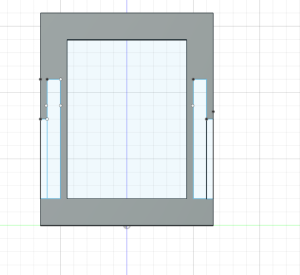
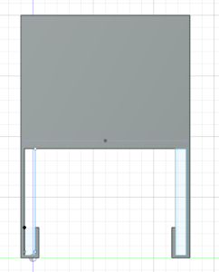
When it comes to the coils, it seems like the height of the coil is to big for the carrier to pass over, which was not anticipated until recently as previous tests showed that just the carrier itself could go over the coil, but now with the circuitry added and weight being an issue now, this is a risk since if the coil isn’t short enough, then we run into the issue where the carrier would just stop at the speed-up coil, and not be accelerated by the coil, which are detrimental to the project. The point of the coil is to allow the carrier to be propelled across the track and if the height is an issue such as now, then we can not propel the carrier across the track. With this being an issue, we arrear now looking into altering the design of the spool for the coil as well as considering other changes like reducing components on the carrier as well as removing the battery form the carrier in order to reduce the weight of the carrier which would then increase the levitation from the track for the carrier, which would then allow the carrier to pass over the coil easily.


Design Changes

Decided to go with a smaller height for the speed-up coil spool in order to allow the carrier to pass over the coil when traveling on the track, since weight is now a huge factor to this project.


Schedule

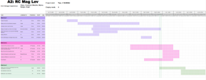
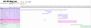
No change in our schedule.

Test

Response Time: 

We found that we had a response time of 50ms. This estimate is what we found to be a ceiling estimate of the longest response from the carrier to track. Based on the results we believe that we should be able to position the stops between the carrier and coil to be able to account for the delay and properly propel the coil in a sightly manner.  We anticipate that the Arduino response time will be somewhat variable and should be fast enough for our needs despite the added delay that comes from the serial Bluetooth communication. No design changes are needed based on the results of this test. 

Speed Up Coils

When it comes to testing the speed-up coil, we tested which coil produces the most magnetic field based on the radius, the type of AWG Copper Wire, the amount of current going through the coil, turns, etc.

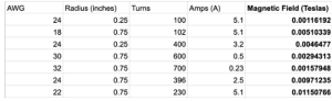
With these results, we can easily tell that the coil with 22 AWG with a radius of 0.75 inches, 230 turns and 5.1 Amps which produces .012 Tesla, that this coil is the one that produces the most magnetic field. When it comes to the final product, we know that this coil produces a powerful magnetic field, but we need to consider the smoothness of the carrier when it passes over the coil. With that being said, we tested where on the coil the back end of the carrier should be positioned to maximize smoothness and distance traveled from the propulsion. We marked the spool with a sharpie and confirmed visually that the carrier can smoothly travel about one section of the track in length without nose diving and maintaining stability.

Levitation and Stability

The remainder of our test was completed through visual inspection. We looked at how well our carrier levitated and propelled on the track to determine whether they meet our standards. For levitation, we wanted our carrier to continuously levitate regardless of its location on the track. With our final design—2cm magnets with no spacing for the carrier and 2.5 cm rectangle magnets no spacing for the track—we were able to achieve this. For stability, we wanted our carrier to continuously and evenly propel, regardless of location on the track. This was also achieved with this current prototype. Past prototypes magnet shapes caused parts of the track to be attracted to edges of the magnets, causing irregular propulsion. The new design has eliminated this issue.

Team Status Report for 4/20

Risks

Speed-Up Coil:

When it comes to the speed-up coil, the potential risks that are in play are the strength of the magnetic field being produced by the coil, as well as how far the coil propels the carrier along the track. For the strength of the magnetic field, if what is being produced is not strong enough, then that means that we would probably need to alter our design of the project the remove the speed-up coil since that would mean we need to allocate more time and money towards creating morrer coils, and with such little time remaining of the project, is something we would need to consider in terms of potentially removing such coils. As for how far the coil propels the carrier along the track, if the distance is not great enough, that means that we would need to allocate more money towards buying more resources to produce more coils for the track.


Bluetooth Communication:

We currently have implemented a circuit that sends signals between a receiver and a sender. The sender takes readings from the hall effect sensors and outputs a string to the receiver to determine which LEDs to light up. The main risk with Bluetooth communication making sure we can send the signals from the carrier to the track in a timely fashion. There’s a slight delay between sending a signal and the receiver registering it. We need to make sure that the signals are transmitted fast enough to make sure that our carrier does not experience a significant slowdown on the track. We want our carrier to exhibit constant speed throughout the demo at least. To mitigate this we will need to be very precise with how and when decide the hall effect sensors are high enough to transmit. Trial and error are likely needed. 


Small Gap Between Track and Carrier:

Our new carrier design has less space between magnets but still has a small gap between the track and the carrier. This gap is limiting space for the speed up coils and limits levitation. If this is not fixed, the speed up coils will not be able to adequately propel the carrier and the lack of room for levitation can cause the rails on the track and the hook on the carrier to have a lot of friction, causing damaging to both. We plan to cut the hooks from the carrier.


Design Changes


Track now has rectangle magnets spaced out 1cm. The carrier use circle magnets that have no spacing betweening each other.


Schedule:

We are currently on schedule.

Team Status Report for 4/6

Now that you have some portions of your project built, and entering into the verification and validation phase of your project, provide a comprehensive update on what tests you have run or are planning to run. In particular, how will you analyze the anticipated measured results to verify your contribution to the project meets the engineering design requirements or the use case requirements?

Verification is usually related to your own subsystem and is likely to be discussed in your individual reports.
Validation is usually related to your overall project and is likely to be discussed in your team reports.

Use Case Requirements, Testing Plans: 

Fast response time of under 3 seconds (Tentative)


  • We will measure the time it takes from signal dispatch to the actual stopping by logging in to the Arduino terminal


  • We know we will have satisfied the use case requirements if our response time is less than 3 seconds
  • We anticipate that because of the responsiveness of the Arduino and the speed it can transmit signals achieving a response time below 3 seconds should be very feasible

Levitation System


  • We will manually verify our carrier’s height above the track with physical measurements. 
  • We will have met our design and use case requirements if we can achieve a levitation of 0.8 inches. 
  • The levitation distance will be measured from the track’s top to the carrier’s bottom
  • We currently have achieved a levitation of 1 inch, meeting our requirement


Object Obstruction Module


  • We will manually set up instructions on the track and measure the distance at which the carrier stops before the obstacle. 
  • We ideally want the carrier to stop at least one carrier length before the obstacle at a minimum of 2 centimeters (design requirement) before the obstacle given the limitations of our ultrasonic sensors. 
  • Overall we want our carrier to be 75% accurate when detecting obstacles.


Speed (Tentative)

  • We will use a speed detector as well as look at the peak points of the linear hall affect sensor to detect how fast the carrier travels from one coil to the next
  • We previously stated that we would want our carrier to travel around 2 mph


Risks:

Strength of Magnetic Field From Coil

Our track relies on solenoid coils to help propel the carrier across the track. With the limited budget for the project, we are hoping to maximize the magnetic field so then it would be strong enough to propel the carrier a large enough distance, to decrease the amount of coils needed on the track. Since it is unknown of the effects of the currently designed coils with the track and carrier, we run the risk of having a coil not being strong enough, thus the need to redesign the coils which will only take up more time and more resources.


Friction from Design

Our current 3D-printed track has a guiding rail. This was created to support the carrier but it is limiting the carrier’s mobility. Currently, several gaps between the carrier and track are too small. This has created little room for the carrier to levitate, limiting the levitation magnets. Additionally, the friction between the track and carrier would make it harder for the speed-up coils to propel the track. 


Wireless communication

Our project is dependent on the carrier circuit communicating with the track circuit. The stop, start, and speed system requires that the linear hall effect can communicate with the H-bridges to adjust the speed of the carrier through the speed-up coils. The obstruction system requires that the ultrasonic sensor can communicate with the H-Bridge to stop the carrier if there is something within 10 cm of the carrier. We are attempting to do this through the HC-05, a Bluetooth communication — that can allow Arduino to communicate. We are still working on writing the code that would allow this communication to take place. Not being able to complete this code would mean there is no way for either sensor to communicate with the track.


Design Changes:

None to be reported


Schedule:

No update to schedule. We are on track.


Team Status Report for 3/30

Risks:

With the speed-up coil, the risks that can occur are related to the strength of the magnetic field produced, as well as the timing of activating the coil for the best result for propelling the carrier across the track. When it comes to the strength of the magnetic field, we need to make sure that we maximize the magnetic field produced to be strong enough to push the carrier from one coil to the other. Initial tests with just the carrier as well as cardboard prototypes show encouraging signs that we are able to push the carrier to some capacity, but there is room for improvement, such as increasing turns and radius of these turns, as well as using better AWG for copper wire since we are stuck using 18 AWG which is thicker than the preferred 24 AWG wire since 24 AWG allows for easier and tighter turns, which would only improve magnetic field strength. When it comes to the timing of activating the coil, there is a huge difference in terms of where the carrier is located on the track and the direction in which the carrier is traveling. Based on initial readings, when we program the carrier to travel to the right and the track is positioned from left to right, the propulsion of the carrier is optimized when the back of the carrier is located within the range of halfway of the coil, to the right end of the coil. When we program the carrier to travel to the left, and the track is positioned as mentioned before, the propulsion of the carrier is optimized when the carrier is close to an inch before reaching the right side of the coil, meaning that the magnetic is stronger to the point where it attracts the carrier to pull it towards the coil, and of course with timing the coil to turn on and off, could excel the carrier well past the coil. The timing is crucial not only for optimizing the propulsion of the carrier but also for ensuring stability for the carrier on the track since, due to testing and figuring out the positioning of the carrier based on the coil, there would be occasions where the carrier would do a flip, do a nose dive, etc.

In order for the carrier to move and appropriately respond to stops and obstructions, it must be able to communicate with the speed up coils and the track. This is done through having the arduino on the track communicate with the arduino on the carrier. HC-05 does this through communicating through serial outputs but each arduino has its own unique configurations for serial outputs. Given that the first serial is being used for plotting to the serial plotter or printing values to the serial monitor, this one can not be used. Some arduinos come with other built in serials or require specific serial libraries. Figuring out how to have both arduinos print from serials that can communicate with each other has been a difficult. However, with some more research, we believed we will find the correct serial/serial library

Some of the ultrasonic sensors would switch between two very different values suddenly when it was being tested though the sensor was not being moved. For example, the sensor was switching between 2cm and 800cm at some point.  We believe this is a result of a faulty part since the issue disappeared once the sensor was switched out. To monitor this, a LED is set up to light up if an object is a particular distance away and the distance is being printed into the serial monitor for the carrier ardunio.

Design Changes:

A rail was added to the two-to-one CAD design to assist with stability.

Schedule:

Updated schedule below


Team Status Report for 3/23

Risks

One major risk for our project is the speed-up coils. While working on the solenoids, we realized that we didn’t produce enough magnetic field to propel our carrier. We confirmed with testing with a singular magnet that the magnetic field we have produced is strong enough to propel the magnet, but the goal of these coils is to propel the carrier across the track. We have made changes to our solenoid such as changing the radius, changing the amount of turn, and  the location of the solenoids on the track. We calculated that we produced a stronger magnetic field but have also run into the same issue of not being able to propel the carrier. This poses some risk for our project since the MVP heavily relies on being able to move the carrier along the meter long track.


Another risk for our project is the stability of our carrier. The stability of our carrier is determined by the ratio and of magnets along the track and carrier and the design of the track and carrier. We started working on the two-to-one track design due to issues with stability in the one-to-one option. While this was slightly more stable, we noticed that magnets would get stuck in gaps in between groups of magnets. The stability of the carrier on the track affects the ability for the whole maglev train to be successful.


Design Changes:

We have decided to make multiple changes to our solenoids such as increasing the radius of the turns, the location of the solenoid on the track, etc. in order to help produce a stronger magnetic field to propel the carrier. We found out that using the casing of the 24 AWG Copper Wire allows for a larger radius for the turns as well as more stable and tighter turns, thus helping out in producing a larger magnetic field.


We have ordered rectangular magnets. They will be an alternative to the two-to-one circle magnet track with less possibility of magnets getting stuck do to their being no major gaps between the magnets (they create a straight line).

We have a CAD design with a guide way for the track. This would limit the movement of the track, decreasing the chances that the track would flip over.


Schedule Change:

We are on schedule


Team Status Report for 3/16

Risks

One major risk in our project currently is interpreting data retrieved by the linear hall effect sensor. While this device met our specification needs, it is very sensitive to close-range changes in magnetic field. For example, moving a magnet across the magnetometer will cause high peaks and lows on the graph produced by our Arduino, signifying great changes in the magnet field. However, moving a far magnet across the magnetometer produces little change in the magnet field. This behavior will force us to do extensive signal processing to interpret the magnetometer data so we can 1) establish a baseline sinusoidal for when the carrier is regularly moving along the track and 2) properly detect peaks in the magnetometer from the speed coils or approaching a stop (another magnet).

Another risk comes from creating a stable carrier. Currently, the prototype for the one-to-one carrier and track magnet design levitates but is sensitive to sudden movement, even when the sides of the track are elongated. Given we have not tested this design with our speed up coils, this can cause some problems once the train starts to move. We were previously given a design suggestion from course staff that have attempted to implement. This design involved a one-to-two carrier and track magnet design. However, due to gaps between magnets in the track, the sides of the carrier magnets would be attracted to the sides of the track magnets due to the gaps in track. Given that the magnets are circular, we could not come up with a solution to this problem without considering buying smaller magnets to but in these gaps or using new, straight magnets instead.


We found with our current propelling coils that we are not generating as much force as we would have expected. We need to make sure that we have the coils as close to the carrier as possible to ensure the magnetic field is at its strongest. We also will look to replace the bolt in the middle of the coil with a plastic core to reduce the inductance of the solenoid so that we do not need to drive as much voltage to our bridge. 

Design Changes:

Spacing between the magnets has further reduced in the straight-away one-to-one design to 0.5 cm between each magnet in the track and carrier. Spacing for the straight away two-to-one design has changed from 1cm to 0.5cm to no space. Given the problems with this design, we expect to see more changes in the following week. Make our propelling coils larger in hopes of creating larger magnetic field strength, and replacing the steel core with a plastic or somehow an air core. 

Schedule Change:

We have changed our schedule to be more accurate to our current design, responsibilities, and progress on those responsibilities.


Team Status Report for 3/9

Risks:

A major risk in our project currently is ensuring the carrier can stably levitate along the track. While the carrier can levitate in the initial straightaway prototype, this levitation is not straight or stable. Future designs need to consider adding longer elongated carrier sides and a smaller gap between the track and the carrier’s elongated sides. We are also considering having two lanes of magnets on the track instead of just one to account for the stability, automatically.

Design Changes:

Spacing between magnets has reduced

The length of the extended sides is larger in hopes of providing more stability

Schedule Changes:

Pushed back prototype 2 design

A was written by Angel Nyaga, B was written by Emanuel Abiye, and C was written by Myles Mwathe


Part A: Global Factors

The product solution meets global factors by providing a user-friendly interface and an educational opportunity to any user, regardless of their country of origin. The user interface in our project will either be a remote or a series of buttons. Both systems will have buttons instructing the track to go from one part of the track to another. While we will provide instructions on how to use the track in English, understanding how the user interface works is not limited to English speakers. Additionally, the electromagnetic principles that can be taught using the remote-controlled maglev train are not limited to English speakers because these lessons are primarily visual. Therefore, our product solution is accessible to a wide variety of individuals of different languages, cultures, and experiential backgrounds.


Part B: Cultural Factors

When it comes to MagLev trains, only three countries have fully implemented them into their transportation systems: China, Japan, and South Korea. Certain factors such as the cost of implementing MagLev trains into their transportation systems, not being able to use the current infrastructure for MagLev trains, etc. play roles in why nations are not looking into implementing MagLev trains into their transportation systems. What we want out of HoverRail is to serve as a learning tool, to show the benefits of MagLev trains. With such knowledge on these kinds of trains as well as seeing the benefits and comparing the pros of MagLev trains with current model trains, we want it to help change the minds of nations and their government or their transportation agency to see how beneficial and more efficient transportation would be in their nation if they replaced current trains with MagLev trains, regardless of cost and not being able to use current infrastructure. We also hope that beyond influencing the opinions of nations, we want it to help influence individuals and their thoughts on MagLev trains. Some people may have never heard of this kind of train and may only be used to the current trains in their nation, and once we introduce HoverRail to such individuals, we hope that we influence their beliefs on transportation, such that these individuals would want to see a fully scaled MagLev train being implemented in their country. There might also be those who are totally against innovating the train systems in their country and may want to stick with the traditional method or stick with the traditional train designs. For these individuals, though it may be hard to fully influence them from their beliefs, we hope that the introduction of HoverRail could spark some sort of dialogue or some contemplation of this new design of trains amongst these individuals, and hopefully to the point where they ease up on their beliefs and become more accepting of innovation and replacing traditional train designs with MagLev trains.


Part C: Environmental Factors

HoverRail does not create much waste leading to low environmental impact. Our MVP will be at most 1-meter long and the carrier will not have a massive size. HoverRail does pose safety concerns when it comes to people wearing conductive materials near the track and carrier. Because of this, warning signs will be provided very clearly with the product. Our product is intended to be durable and reusable. We want electromagnetics students to be able to use HoverRail as a learning tool, and such a tool needs to be durable and readily available multiple times over. HoverRail is not meant to be discarded after a certain amount of uses, the users are meant to keep using the trainset as many times as possible. Lastly, when it comes to the consumption of natural resources as it pertains to HoverRail, we aim to make all of the materials needed to operate our train system easy to attain. We want HoverRail to be easily replicated in classrooms or home environments. Because of this, we avoided the use of obscure materials like Liquid nitrogen which increases the strength of the magnets by dropping the temperature.

Team Status Report for 2/17

Risks:

The main risk with our project is that we aren’t able to get our Arduino integrated duty cycle for the voltage to vary the current in the speed coils. This would mainly affect the propulsion system. In the case we can’t get the magnetic propulsion system functional we would pivot to a mechanical wheel system and have some type of battery or motor for the carrier. Achieving levitation and stability with levitation as well is a risk. To mitigate this risk we have designed our carrier with elongated sides to slightly contact the track to make sure it does not fall off. 

Design Changes:

  • Lidar to Ultrasonic Sensor with Blockage system
  • Digital Potentiometer to H-Bridge with speed up coil
  • Straight-Away track for MVP 

Schedule Changes:

  • Push back when we design speed up coils
  • Push back prototype 2
  • Since we are no longer using the lidar sensor, we have freed parts of our schedule. Therefore, we have time to push back parts of our schedule

A was written by Angel Nyaga, B was written by Emanuel Abiye and C was written by Myles Mwathe.

Part A:

Given that our product involves a user interface, there is good reason to consider what safety mechanisms the product has. This product is intended to have the user have as little interaction with the circuit as possible. To get the train to move, a button, separate from the main circuit is pressed. This little interaction protects the user from the possibility of being hurt by components of the circuit. 

Additionally, magnetic fields are often associated with negative health effects. This is only true when someone is in contact with a high amounts of magnetic fields. Since our system is small, a small amount of current is required to power the system. This means a small magnetic field is produced, meaning the user is not in danger.

Lastly, we want to advise people with magnetic or conducting materials to steer clear of the product. Given that our system is dependent on magnetism, there is a high possibility a conducting or magnetic component can interfere with the system without our control. This interference could result in damage to the product and harm to anyone near the product. For this reason, we would put up a visual disclaimer to anyone approaching the product with conducting and magnetic material.

Part B:

Our project aims to target train enthusiasts and those interested in Maglev Trains and would like to learn more about them. Our product offers an interactive learning experience for both kinds of users. For enthusiasts, we wanted to make sure that our product mirrored real life Maglev Trains and their functionality, with such components being the levitation and wanted to ensure authenticity to our product that can stand out to similar products. With the overall quality gap we plan on having compared to current MagLev model train sets, we believe that we can successfully cater to such users. And with such a gap mentioned before, train enthusiasts would be fine with our proposed cost for our product. For those that primarily would want to learn more about MagLev Trains, we are allowing our product to take in user input, allowing users to experiment with how MagLev trains would respond to such inputs. With examples such as affecting the speed, or having a carrier move from one stop to the next, or manipulating the current throughout the track, we want these users to learn how the MagLev carriers react to these changes, and have these reactions be as accurate as possible to an actual MagLev train. Again, with how wide we expect the gap to be compared to current MagLev model train sets, we believe that the cost accurately represents the wide variety of experiments and knowledge the user can learn from our product, and would be fine with the proposed cost. Overall, we are hoping to have a mutual appreciation of MagLev trains from both kinds of users, and possibly allow train enthusiasts to become the kind of user that would want to learn more about MagLev trains, and allow those that want to learn more about MagLev trains become train enthusiasts themselves.

Part C:

We are mindful of the current model maglev trains on the market and their prices currently. The most functional maglev train set that allows for propulsion goes for around $450. Some simpler models cost less but don’t have propulsion systems beyond the user pushing the train along the track manually. Some maglev model trains require materials like liquid nitrogen which may be expensive and hard to obtain for the average user of our product. 

Given that our budget for the project as a whole is $600 and that most of the components of our MVP are relatively inexpensive, staying below a price of $450 should be relatively easy. Since we are pivoting our design to use ultrasonic sensors and magnetometers instead of a LiDAR system, we not only simplify the complexity of implementation but the overall cost of our project as well. The magnets we would be using for the product are also relatively inexpensive given that the load of our carrier won’t be heavy enough to justify having to use stronger, more costly magnets. We aim to make our product accessible to people who want to learn about electromagnetics and the average train hobbyist so we don’t want there to the price point of the product to be an accessibility limiter for users. When our process becomes optimized for production we should be able to cut the costs of the product even further since we wouldn’t be doing prototyping and experimentation. 


Team Status Report 2/10

Team Status Report for February 10, 2024

Risks

  • Levitation not working. 
    • We have a backup system with mechanical wheels. We will test the levitation system early on to make sure it’s sufficient 
  • Things ordered don’t show up on time
    • Working in slack time into the schedule. 
  • Integration not working out. 
    • Prioritize levitation and propulsion and work with the functional components. 
  • Speed and Slow not Implemented. 
    • Try different methods to implement speed-up/slow-down, we’ll look into different tracks and circuit designs. 
  • RFID stops not functional. 
    • We’ll make sure the train does a complete loop around the track which can be triggered by the user. 

Design Changes

The LiDAR may be changed to an ultrasonic sensor or something lighter and simpler. The LiDAR may be too complicated for our needs. 

Schedule Changes

In the future, we will try to make it more clear that our tasks are parallel.