Emanuel’s Status Report for 3/16

Mandatory Lab (4 hr.)

  • Met with professor and TA to discuss recent design report
  • Discussed with the team about work distribution

Design Research and Self-Time (8 hr.)

  • Worked on the speed-up coil
  • Looked more into how to interpret readings from Linear Hall Effect Sensor
    • Readings from a magnet depending on distance
    • Readings from speed-up coils

Progress:

We started looking into how to interpret the readings from the Linear Hall Effect. At first, we had difficulty interpreting the data, but a discussion with the professor cleared up the confusion. I then wanted to see what the fixated readings from a single magnet look like depending on how far the magnet is from the sensor. At first, when looking at the readings from the magnet with the professor, I was confused about why the readings were decreasing, as they should have increased from the normal base rate of 510, indicating no magnetic field. However, after further research, I learned that it depends on the polarity or the side of the magnet facing the sensor. So, for my individual research with the sensor, I made sure to collect data from both sides of the magnets. The following are the data that I collected:

Linear Hall Effects Readings:

(Same polarity)

3 inches away: 511

2 inches away: 514

1 inches away: 534

.5 inches away: 600

.25 inches away: 745

(Opposite polarity)

3 inches away: 509

2 inches away: 507

1 inches away: 491

.5 inches away: 416

.25 inches away: 284

From this, it’s clear to see that we need to take distance into account if we want to get a clear, distinct change in magnetic field readings when the carrier is running on the track when the carrier is approaching a speed-up coil, etc.

I also worked with Myles on improving the speed-up coil since, for some reason, it decided to no longer work from the first time I created them. We made two new designs for the solenoids with different turns and lengths. We also made sure to find the calculations of these solenoids and share them with the professor and the TA to make sure we were approaching this correctly. After consulting with the professor and clarifying measurement and data, we realized that we were not generating as much magnetic field as we actually anticipated, and we needed to look into incorporating new coil designs.

Schedule:

Since we recently changed our schedule, we are currently on track with the new schedule.

Next Week’s Schedule:

Create new solenoid coils with stronger magnetic field output and implement them into the track to test propulsion with the carrier. Since Myles and I are away at the NSBE National Convention, we will put our complete effort into finalizing these coils. The only thing left for our group is finalizing the track and carrier design and finally printing them.

Team Status Report for 3/16

Risks

One major risk in our project currently is interpreting data retrieved by the linear hall effect sensor. While this device met our specification needs, it is very sensitive to close-range changes in magnetic field. For example, moving a magnet across the magnetometer will cause high peaks and lows on the graph produced by our Arduino, signifying great changes in the magnet field. However, moving a far magnet across the magnetometer produces little change in the magnet field. This behavior will force us to do extensive signal processing to interpret the magnetometer data so we can 1) establish a baseline sinusoidal for when the carrier is regularly moving along the track and 2) properly detect peaks in the magnetometer from the speed coils or approaching a stop (another magnet).

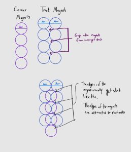
Another risk comes from creating a stable carrier. Currently, the prototype for the one-to-one carrier and track magnet design levitates but is sensitive to sudden movement, even when the sides of the track are elongated. Given we have not tested this design with our speed up coils, this can cause some problems once the train starts to move. We were previously given a design suggestion from course staff that have attempted to implement. This design involved a one-to-two carrier and track magnet design. However, due to gaps between magnets in the track, the sides of the carrier magnets would be attracted to the sides of the track magnets due to the gaps in track. Given that the magnets are circular, we could not come up with a solution to this problem without considering buying smaller magnets to but in these gaps or using new, straight magnets instead.


We found with our current propelling coils that we are not generating as much force as we would have expected. We need to make sure that we have the coils as close to the carrier as possible to ensure the magnetic field is at its strongest. We also will look to replace the bolt in the middle of the coil with a plastic core to reduce the inductance of the solenoid so that we do not need to drive as much voltage to our bridge. 

Design Changes:

Spacing between the magnets has further reduced in the straight-away one-to-one design to 0.5 cm between each magnet in the track and carrier. Spacing for the straight away two-to-one design has changed from 1cm to 0.5cm to no space. Given the problems with this design, we expect to see more changes in the following week. Make our propelling coils larger in hopes of creating larger magnetic field strength, and replacing the steel core with a plastic or somehow an air core. 

Schedule Change:

We have changed our schedule to be more accurate to our current design, responsibilities, and progress on those responsibilities.


Myles’s Status Report for 3/16

Personal Accomplishments:

  • Lab Meetings (4 hrs):
    • met with the team to discuss work distribution with people being away from campus
  • Indiviudual Work (8 hrs):
    • designed multiple propelling coils and tested and calculated their magnetic strength
    • Wrote an initial script to work with remote control and ultrasonic sensor.

Progress:

I worked with our ultrasonic sensors and remote controls this week and interfaced with them through the Arduino microcontroller. I wrote initial scripts to get readings from the ultrasonic, so we know what to program when attaching the ultrasonic to the carrier. I worked with Emanuel and we designed a couple of speed coils (solenoids). We did calculations of how much magnetic strength each solenoid would be able to output. We found with our current solenoids, we are achieving magnetic fields of about 4.5 * 10^-2 Tesla, and 4.5 teslas when accounting for the steel core, which in our case is a standard bolt.  Given this calculation, we found we were not generating as much force as expected when setting up our coils underneath our carrier. We had issues understanding how we could connect a power supply to our h-bridge so we found it difficult to feed sufficient amounts of current to our solenoid. The primary option to mitigate this is to make our solenoid larger with more turns and make those turns tighter which would lessen our length factor when it comes to magnetic strength.  When it comes to remote control we found a remote control, transceiver set which is fairly simple to integrate using a microcontroller. We will have users use this remote control to control this train. We unfortunately were not able to get to printing our track and carrier we hope to finish our CAD design this week and have the pieces printed while Emanuel and I are away at the NSBE national convention.

NOTE – I realized I made an error in not accounting for the fact that the magnetic field strength of the solenoid drops off drastically with a factor of R^3. We are not getting as much force as expected because the coils are too far from the carrier. It would help however to have our coils take up a wide radius and have more turns as well.

Next Week Deliverables:

  1. Have CAD track and carrier ready to 3D print
  2. Make 4 solenoids with magnetic strength output at least double of our current design.

Angel’s Status Report for 3/16

  • Weekly Team Meeting (2hr)
    • Discuss design changes for the track and carrier t
    • Discuss how to best implement the ultrasonic sensor and linear hall effect sensor
  • Mandatory Meeting (4hr)
    • Discuss design changes for the track
    • Go over feedback from design review
  • Independent Work (6hr)
    • Change one-to-one carrier/track magnet design
    • Reattempt two-to-one carrier/track magnet design
    • Test linear hall effect sensor


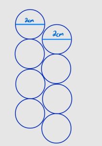
Through out this week I spent time working on the design of two prototypes. I rebuilt the straight away one-to-one track with less spacing between the magnets to stop magnets from the carrier getting stuck. While this helped with that problem, it made it clear that a one-to-one system is unstable. I attempted to redesign the two-to-one carrier/track. In this design two aligned rows of magnets were placed on the track. However, given that the magnets are circular, parts of the track had gaps as seen in the picture below. These gaps resulted in carrier magnets getting stuck on the track.  I have created a new design in which the magnets (2cm diameter) are misaligned by 1cm. I plan to implement this design early next week.

I also tested the linear hall effect. I tested how the linear hall effect behaved when a magnet was near the sensor, far from the sensor and when a magnet moves along it. I used this information to better understand the data I was receiving from the Arduino and how to interpret that information into something usable.


We updated our schedule earlier this week to more accurately reflect what we have complete and what we know hope to complete. Therefore, I am currently on schedule.


Next Week

In the following work, I plan to build my new design for the two-to-one track/magnet design. I also want to work with my teammates to see how to add a speed coil to the one-to-one track/magnet design given its only problem currently is stability. Lastly, I would like to start signal processing for the linear hall effect sensor.


Emanuel’s Status Report for 3/9

  • Mandatory Lab (4 hr.)
    • Met with TA and Professor to discuss feedback from presentation
  • Design Report (4 hr.)
    • Completed the Introduction, Use-Case Requirements, Design Requirements
  • Design Research and Self-Time (4 hr.)
    • Modified CAD design for straightaway track and carrier prototype
    • Worked on the speed-up coil

Schedule:

As of now, we are behind schedule. Again, we would have liked to have our track and carrier printed out, but since we are still waiting for the 3D printing filament, we are still bound to work with cardboard and try to improve our cardboard designs. I also would have liked to have finished at least one speed-uup coil, but I haven’t been able to either because the available copper wires in TechSpark were too thick to complete the 200 turns we wanted or the copper wire wasn’t conducted, meaning that the current couldn’t pass through the coil. This has caused further research to be done in order to find the exact copper wire that is both thin enough to complete the 200 turns, as well as conducted to allow for the current to run through the coil.

Next Week’s Schedule:

  • Fully printed out carrier and track
  • H-Bridge Circuitry w/ Speed-Up Coil

Myles’s Status Report for 3/9

Personal Accomplishments:

  • Lab Meetings (4 hrs):
    • met with the Professor and TA to discuss the design review presentation
  • Indiviudual Work (8 hrs):
    • wrote the testing, validation section, architecture of operations, and bill of materials
    • Wrote initial Arduino script and constructed basic circuit with PWM

Progress:

Behind Schedule – This week I implemented the Arduino script to send PWM inputs to the H-Bridge. The script periodically would switch the direction of the current. We set up a circuit with a miniature propeller as the motor connected to the H-Bridge. With the periodic propeller switch in the script the direction the propeller spins would switch. We are behind schedule in that we still need to design a new CAD track and carrier that addresses our stability issues. Next week, I plan to figure out and research how the ultrasonic and Hall Effect output information and how to read it properly.

Next Week Deliverables:

  1. redesign track and carrier with connection grooves for increased stability
  2. Write the initial script for the hall effect and ultrasonic sensors. The main goal is to figure out how the output of the sensor and how to interface with them with the Arduino.

Team Status Report for 3/9

Risks:

A major risk in our project currently is ensuring the carrier can stably levitate along the track. While the carrier can levitate in the initial straightaway prototype, this levitation is not straight or stable. Future designs need to consider adding longer elongated carrier sides and a smaller gap between the track and the carrier’s elongated sides. We are also considering having two lanes of magnets on the track instead of just one to account for the stability, automatically.

Design Changes:

Spacing between magnets has reduced

The length of the extended sides is larger in hopes of providing more stability

Schedule Changes:

Pushed back prototype 2 design

A was written by Angel Nyaga, B was written by Emanuel Abiye, and C was written by Myles Mwathe


Part A: Global Factors

The product solution meets global factors by providing a user-friendly interface and an educational opportunity to any user, regardless of their country of origin. The user interface in our project will either be a remote or a series of buttons. Both systems will have buttons instructing the track to go from one part of the track to another. While we will provide instructions on how to use the track in English, understanding how the user interface works is not limited to English speakers. Additionally, the electromagnetic principles that can be taught using the remote-controlled maglev train are not limited to English speakers because these lessons are primarily visual. Therefore, our product solution is accessible to a wide variety of individuals of different languages, cultures, and experiential backgrounds.


Part B: Cultural Factors

When it comes to MagLev trains, only three countries have fully implemented them into their transportation systems: China, Japan, and South Korea. Certain factors such as the cost of implementing MagLev trains into their transportation systems, not being able to use the current infrastructure for MagLev trains, etc. play roles in why nations are not looking into implementing MagLev trains into their transportation systems. What we want out of HoverRail is to serve as a learning tool, to show the benefits of MagLev trains. With such knowledge on these kinds of trains as well as seeing the benefits and comparing the pros of MagLev trains with current model trains, we want it to help change the minds of nations and their government or their transportation agency to see how beneficial and more efficient transportation would be in their nation if they replaced current trains with MagLev trains, regardless of cost and not being able to use current infrastructure. We also hope that beyond influencing the opinions of nations, we want it to help influence individuals and their thoughts on MagLev trains. Some people may have never heard of this kind of train and may only be used to the current trains in their nation, and once we introduce HoverRail to such individuals, we hope that we influence their beliefs on transportation, such that these individuals would want to see a fully scaled MagLev train being implemented in their country. There might also be those who are totally against innovating the train systems in their country and may want to stick with the traditional method or stick with the traditional train designs. For these individuals, though it may be hard to fully influence them from their beliefs, we hope that the introduction of HoverRail could spark some sort of dialogue or some contemplation of this new design of trains amongst these individuals, and hopefully to the point where they ease up on their beliefs and become more accepting of innovation and replacing traditional train designs with MagLev trains.


Part C: Environmental Factors

HoverRail does not create much waste leading to low environmental impact. Our MVP will be at most 1-meter long and the carrier will not have a massive size. HoverRail does pose safety concerns when it comes to people wearing conductive materials near the track and carrier. Because of this, warning signs will be provided very clearly with the product. Our product is intended to be durable and reusable. We want electromagnetics students to be able to use HoverRail as a learning tool, and such a tool needs to be durable and readily available multiple times over. HoverRail is not meant to be discarded after a certain amount of uses, the users are meant to keep using the trainset as many times as possible. Lastly, when it comes to the consumption of natural resources as it pertains to HoverRail, we aim to make all of the materials needed to operate our train system easy to attain. We want HoverRail to be easily replicated in classrooms or home environments. Because of this, we avoided the use of obscure materials like Liquid nitrogen which increases the strength of the magnets by dropping the temperature.

Angel’s Status report for 3/9

The following work was completed between 2/25 – 3/9 (week prior to spring break – end of spring break)

  • Mandatory Labs (4hrs)
  • Individual work (6hrs)
    • Finalized straightaway cardboard prototype with cardboard carrier
    • Attempted to create straightaway cardboard prototype with cardboard carrier
    • Modify CAD design for straightaway track and carrier prototype
  • Design Report (6hrs)
    • Complete Design Trade Studies and System Implementation

Through out the past two week, I have spent time further developing cardboard prototypes for the track and carrier maglev. I attempted to create two prototypes for the straightaway track and carrier. The first involved having a 1-1 relationship between the track magnets and carrier magnet. While this design successfully levitated the carrier, there were issues with stability. In attempt to create a more stable design, I created a prototype with a 2-1 track magnet to carrier magnet ratio. Due to errors with spacing (the track magnets were too far apart on the track), this design created a carrier that was attracted to the space between the track magnets, resulting in no levitation. I plan to reattempt this design with less spacing between the track magnets to see if the system will be more stable.

Also, completing the initial straightway track and carrier from cardboard showed that the spacing in the current CAD design of the straightaway track is too large. The best spacing between ends of a magnet is roughly 3 centimeters. I plan to make modifications to all CAD track designs to meet these specifications.


Next Week 

In the following week, I hope to start printing the CAD design for straightaway track and carrier. Secondly, I would like to start working on a prototype for the oval shaped track. Lastly, I would like to start working with the ultrasonic sensor and the hall effect to start to design the start, stop, and speed system.

Emanuel’s Status Report for 2/24

This Week’s Updates:

  • Mandatory Lab (4 hr.)
    • Sat and gave feedback to other team’s design presentation
    • Had to prepare and give our team presentation for our team design
  • Team Meetings (6 hr.)
    • Created a cardboard prototype 
      • Track and test levitation and stability
    • Implemented magnets with the cardboard prototype 
      • Track and test the strength of magnets
    • Adjusted CAD design metrics based on results from cardboard prototype
  • Design Research and Self-Time (2 hr.)
    • Looked into alternative ways to power the nano Arduino
      • Nano needs wireless power since it is moving on the track
    • Soldered battery with wires to the nano
      • Tested for any heating, current/voltage loss, whether the component works
    • Researched ways to decrease the amount of voltage loss when connected to the nano
      • Alternative batteries (Lithium batteries)
      • Implement a switch in between the nano and the battery (most likely solution to go with)

Schedule:

As of now, we are behind schedule. We would have liked to have our track and carrier fully printed out by now, but due to our order request being rejected, we had to create an alternative cardboard prototype for testing. Though we are behind schedule, the cardboard prototype really helped us add and finalize certain details and components for the track and carrier.

Next Week’s Schedule:

  • Fully printed out carrier and track
  • Whole H-Bridge circuitry done (at least one coil)

Myles’s Status Report for 2/24

Personal Accomplishments:

  • Lab Meetings (4 hrs):
    • Attended section’s Design review presentations and gave constructive feedback
  • Team Meetings (6 hrs):
    • Wrote the design review slides and finalized details for MVP
  • Research (2 hrs):
    • Looked into PWM through Arduino and found scripts to output PWM to the input pins of the h-bridge
    • Worked on a simple LED circuit to showcase PWM and the ability to raise and lower the duty cycle for the LED

Progress:

Behind Schedule – We need to change our CAD design for the carrier and track and have not made as much progress regarding propulsion. This week we worked with a cardboard prototype to see the feasibility of levitation and achieved a levitation of over an inch.  We will be doing the CAD development of the track and carrier in parallel with the H-Bridge circuit.

Next Week Deliverables:

  1. redesign track and carrier with connection grooves for increased stability
  2. Implement PWM for the input pins on the H-Bridge to create the propulsion force