- Mandatory Meeting (4hr)
- Interim Demo
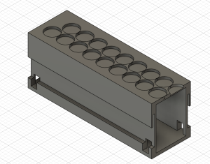
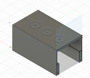
- Adjust CAD Design to match design requirement
- Independent Work (8hr)
- Adjust CAD Design to match design requirement
- Work with two linear hall effect sensors
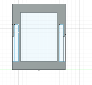
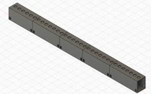
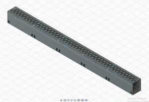
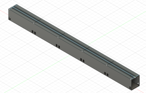
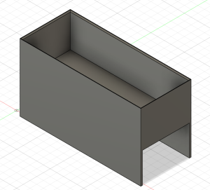
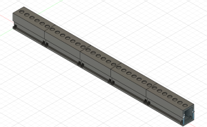
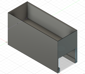
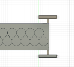
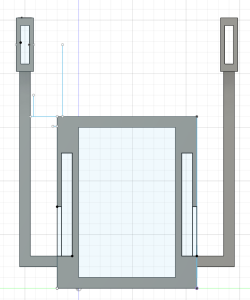
This week, I worked on updating the CAD designs we have to match our design requirements. There were several issues with the 3D printed version of our design. One major problem was there were very small gaps between the track and the carrier. This limited the mobility of the carrier, which would affect the carriers ability to levitate and propel. I adjusted the gaps between along the rail of the track to be wider. Also, with the current design, the carrier could levitate at most 1 cm. Given that our cardboard prototypes levitated 1 inch (2.54 cm), this gap is not large enough. Also, speed up coils will be placed directly above the track, something that could increase the height the carrier levitates. This gap was adjusted to 3.5 cm to allow the carrier room to levitate as much as needed.
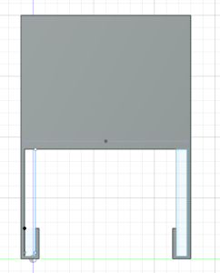
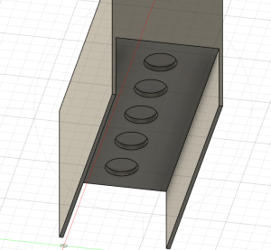
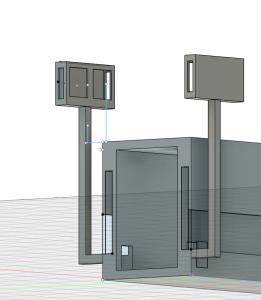
I also worked on the stops for the track. In order for the carrier to detect a stop, a magnet has to be within 1.5 cm of the magnetometers. I created stops along the track that are 4 cm above the track to account for carrier levitating, the speed up coils, the thickness of the 3D printed carrier and breadboard, and the height of the linear hall effect sensor with the magnetometer. The stops are also design to be 1cm away from the carrier.
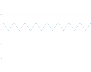
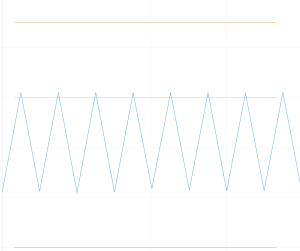
I also worked on adding solidifying the ranges for the magnetic field of different stops. The magnetic field values that determined if the carrier were near a stop all worked within 1.5 cm but all had different gaps between the cut of value and the value within 1.5 cm. For example, the right magnetometer values were too high for the negatively polarized magnet, meaning the magnet could be significantly further than 1.5 cm to get a good reading. While this isn’t a problem, it would be good to be consistent with the gap between the cutoff and the expected value. I adjusted these values so this gap was around 50 units for each possible stop.
Next Week
I would like to print updates to our prototypes to see if they match expectation.