Angel’s Status Report for 3/23

  • Ethics Meeting (2hr)
    • Discusses Ethics of our project with class
  • Independent Work (10hr)
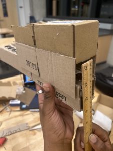
    • Construct cardboard model of two-to-one carrier/track magnets design
    • CAD design for one-to-one carrier/track circle magnets design
    • CAD design for two-to-one carrier/track circle magnets design
    • CAD design for two-to-one carrier/track rectangle magnets design
    • Determined a way to distinguish stops with a magnetometer


Through out this week, I worked on solidifying the dimensions for the one-to-one track/carrier magnet design and the two-to-one track/carrier magnet design. The main changes to models involved spacing out the magnets on the carrier for the two to one magnet. This mainly do to not having enough magnets when I constructed the cardboard prototype but this design was significantly more stable than the one-to-one design but also levitated higher. However, there were still some issues with the magnets getting stuck in between gaps in the track. This was a large reason why we decided to order rectangular magnets


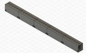
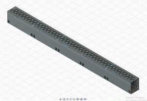
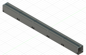
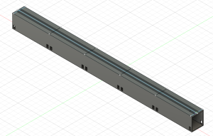
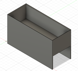
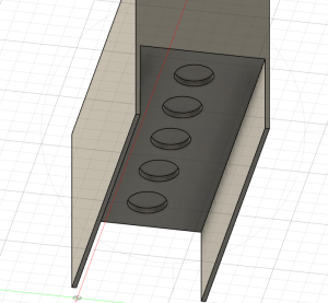
I also constructed CAD models for the different designs. For track designs, I created  the  one-to-one track circle magnet design, the two-to-one track/carrier circle magnet design, and the track design for the two-to-one track/carrier rectangle magnets system(pictures below). The circle magnet designs are based of the finalized dimensions from the cardboard prototypes. Since the rectangle magnets have not come in yet, this design was based off of predicted behavior based on what we have seen with the circle magnets and the dimensions of the rectangle magnets. One major consideration for the rectangular design is how to orient the magnets. Currently, the longer side of the rectangle is along the track and  there is large gap between the lines of magnets. While the magnets are less likely to get stuck since it is a straightaway, sudden movement in the carrier could result in sides of the magnets getting stuck like in past designs. I would like to create a cardboard prototype of this structure then edit the current CAD design based on the results.

One-to-one track/carrier circle magnets
Two-to-one track/carrier circle magnets
Two-to-one track/carrier rectangle magnet (2mm between lines)
Two-to-one track/carrier rectangle magnet (10mm between lines)
Carrier
Bottom of Carrier
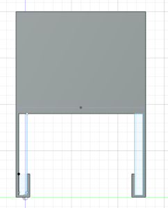
I also created  a derivative of the one-to-one design with a guiding rail for the carrier. This would be in place to help with the stability. This was difficult to construct with cardboard so I would like to print this soon to see if the dimensions of the rail properly account for the height of levitation and sudden movements with the carrier.

One-to-one guided design
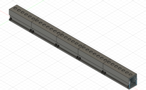
Side of one-to-one guided design
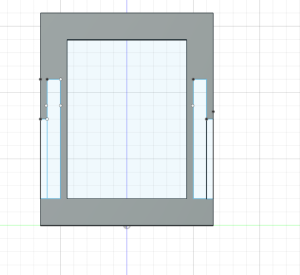
Carrier guided design
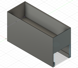
Side of carrier guided design
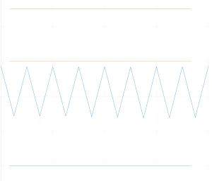
I also worked with magnetometers to attempt to make a stop start system. This was done  though attaching two magnetometers to face opposite sides of a breadboard to simulate the sides of the carrier. I tested how the plot changed as I moved magnets along both sides and switched their polarity while adjusting the sensitivity of the magnetometers. Following a few tests, I noticed that the amplitude of the signal on the plot changed based on the polarity of the magnets, the amount of magnets, and the magnetometer the magnets was in front of.  Based of this, I think a baseline signal can be created and significant changes in either side of the signal can represent a stop.

No Magnet near either magnetometer
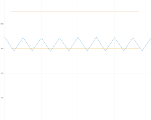
Negative polarity near magnetometer 1
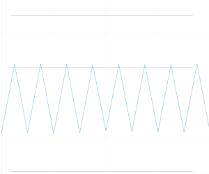
 

Negativity polarity near magnetometer 2
Next Week

Next week, I would like to work on making more carrier designs.  Also, I would like to print some portion of all the above designs to see if there are any major design issues I missed. I would also like to continue working with the magnetometer and start working with the ultrasonic sensors to make a full start, stop system.

Team Status Report for 2/24

Risks:

Stability: We still have some work to do on finalizing the length and other components when it comes to stability, but our whole project focuses on whether the carrier could levitate smoothly while traveling around the track. This poses a huge risk to us and really determines whether or not we can continue making progress on our project, as well as adding a risk to meet our new proposed MVP. When working on the cardboard prototype, we realized that whenever we placed our carrier on the track, the carrier would jump off the track to the side. We kept altering the thicknesses and the length of the sides on the carrier. We looked into increasing the length of the carrier itself which seemed to help out a bit alongside the new lengthened sides. We have also discussed altering the design of the support system on the carrier as well as the actual track itself to allow for more support and canceling any chances of the carrier jumping off as previously stated. If our plans for stability don’t meet our expectations, we can pivot into altering the support portion of the carrier, i.e. having wheels ride along the track instead of lengthened sides.


Propulsion: Another risk we can encounter for this project is making sure our H-Bridge and Arduino work perfectly with each other to allow for propulsion across the track. This system affects the speed of the carrier and whether the carrier would be able to move at all. This poses a huge risk because as previously stated, any failures of the H-Bridge or the Arduino could mean that we would only have a levitating carrier but it wouldn’t be able to move. Of course we could simply push the carrier across the track but we want our product to stand out to the existing market, thus making this an even more important task. We can look into buying alternative H-Bridge chips and Arduinos if the ones we have doesn’t function as expected, but overall we could look into pivoting towards a mechanical wheel system which would implement some sort of battery or motor for the carrier.


Design Changes:

  • Carrier will be redesigned to have a greater length to help with stability when levitating. With a shorter carrier, there were issues with the carrier rotating on its side and slipping off the track. The carrier’s legs will be thicker and filled in and not hollowed out as shown in the design review presentation, the thicker legs will help with sturdiness as the legs broke after 3D printing. 
  • The track will be redesigned to have grooves where the carrier will contact to ensure greater security when the carrier is moving along the track, and make sure the carrier doesn’t lean awkwardly to one side. 
  • With both design changes, the only cost will be extra time allocated for additional CAD design and the actual 3D printing. Cost is not severe enough for mitigations.

Cardboard prototype with levitation

updated schedule

Emanuel’s Status Report for 2/10

This Week’s Updates

  • Mandatory Lab (4 hr.)
    • Attended the mandatory labs, watched peer’s presentations and provided feedback
  • Working on Presentation Slides (4 hr.)
    • Worked with teammates to complete the slides for presentations
  • Team Meetings (4 hr.)
    • Met with teammates outside of in class hours
    • Worked on components to buy
    • Worked on track design
    • Watched videos to compare different circuit designs

Schedule

I am on schedule according to our proposed schedule. I am scheduled  to be focusing heavily on the 3D Printing components first which I have been accounting for.

Next Week’s Updates

  • Getting Prototype 1 materials
    • 3D Filament
    • Wires, resistors, digital potentiometer
  • Finishing up our proposed designed track
    • Finalizing the design, using filament to start printing
  • Research alternative power circuit methods
    • Some including digital potentiometer
    • H-Bridges