Myles’s Status Report for 4/27

Personal Accomplishments:

  • Lab Meetings (4 hrs ):
    • Watched final team presentations.
    • Provided team feedback
  • Indiviudual Work (8 hrs):
    • Met with team to integrate subsystems for final demo

Progress:

This week I worked on integrating our subsystems with the work I have been doing with the Bluetooth modules. We can programmatically send signals from the hall effect on the carrier to the track to ignite the coil to propel our carrier. The goal for the next week is to integrate this with our track and carrier which we are going to print. I believe that we are going to have stops along our track with alternating polarity. Based on the polarity the hall effect reads will determine which coil will get the signal to propel the carrier. We are on track for the demo on Friday and just need to finish up the details.

Next Week Deliverable:

Finish up final demo logistics

Team Status Report for 4/20

Risks

Speed-Up Coil:

When it comes to the speed-up coil, the potential risks that are in play are the strength of the magnetic field being produced by the coil, as well as how far the coil propels the carrier along the track. For the strength of the magnetic field, if what is being produced is not strong enough, then that means that we would probably need to alter our design of the project the remove the speed-up coil since that would mean we need to allocate more time and money towards creating morrer coils, and with such little time remaining of the project, is something we would need to consider in terms of potentially removing such coils. As for how far the coil propels the carrier along the track, if the distance is not great enough, that means that we would need to allocate more money towards buying more resources to produce more coils for the track.


Bluetooth Communication:

We currently have implemented a circuit that sends signals between a receiver and a sender. The sender takes readings from the hall effect sensors and outputs a string to the receiver to determine which LEDs to light up. The main risk with Bluetooth communication making sure we can send the signals from the carrier to the track in a timely fashion. There’s a slight delay between sending a signal and the receiver registering it. We need to make sure that the signals are transmitted fast enough to make sure that our carrier does not experience a significant slowdown on the track. We want our carrier to exhibit constant speed throughout the demo at least. To mitigate this we will need to be very precise with how and when decide the hall effect sensors are high enough to transmit. Trial and error are likely needed. 


Small Gap Between Track and Carrier:

Our new carrier design has less space between magnets but still has a small gap between the track and the carrier. This gap is limiting space for the speed up coils and limits levitation. If this is not fixed, the speed up coils will not be able to adequately propel the carrier and the lack of room for levitation can cause the rails on the track and the hook on the carrier to have a lot of friction, causing damaging to both. We plan to cut the hooks from the carrier.


Design Changes


Track now has rectangle magnets spaced out 1cm. The carrier use circle magnets that have no spacing betweening each other.


Schedule:

We are currently on schedule.

Myles’s Status Report for 4/20

Personal Accomplishments:

  • Lab Meetings (4 hrs ):
    • Fixed and integrated Bluetooth communication between the track and carrier microcontroller with hall effect sensor
  • Indiviudual Work (6 hrs):
    • Met with TA and worked individually debugging Bluetooth communication
  • Team Meetings
    • finalized final presentation poster and plans for the final demo video
    • coordinated with the team for CAD decisions.

Progress:

This week I worked on debugging the Bluetooth communication between our carrier and track microcontrollers. I had issues reading the bytes I was receiving from the microcontroller that was processing the readings for the hall effect sensors. When i would do to read the bytes being sent I would receive decimal values that exceed the expected values for ASCII. When i would try to convert these bytes to a string the serial monitor would give me bogus output. I checked my circuit setup multiple times and ensured I had paired my HC05 modules correctly and found that the issue was resolved when I replaced the receiving HC05 with a spare. Mostly a component within the HC05 stopped working.

When it came specifically to debugging Bluetooth communication, the Arduino blogs were most helpful, where people would document issues that seemed very similar to mine. Generally reading technology blogs when it came to finding tutorials was also very helpful as well. I generally found the blogs to be more helpful than the videos I came across because the steps were much more heavily documented and often times steps were skipped when it came to creating the video. While I tried implementing the solutions found on the Arduino blogs what really helped me, was going through systematically and replacing components in the circuit. The tutorials only on the blog sites were helpful for high-level understanding

Next Week Deliverable:

Add additional functionality with Bluetooth to enable the carrier to propel based on signals alone.

Personal Accomplishments:

  • Lab Meetings (4 hrs ):
    •  Interim demo
    •  Worked with teammates to discuss work distribution for the Final Demo
  • Indiviudual Work (8 hrs):
    • Created a simple circuit to demonstrate the h-bridge component during the interim demo
    • Completed Bluetooth communication between 2 Arduino Unos

Progress:

For the interim demo, I set up a circuit with our bridge and a mini-propeller to show that we can programmatically control which way the current will flow through or coil. Additionally this week I worked on the Bluetooth communication between 2 Arduino uno modules. Currently, I have a circuit that sends messages from a sender module to a receiver, which lights up an LED on signal reception. Eventually, once we figure out at which point we want to send the signal to power our coils we will have our microcontroller module communicate this way. The main work in the coming weeks is making sure we are sending the signals fast enough, which should not be a problem considering Arduinos are reasonably responsive. Another concern is making sure we are sending the signal for a long enough time to give the coil enough time to pick up the current needed to propel our carrier forward. This will be figured out with trial and error.

Next Week Deliverable:

Incorporate user input with Bluetooth signally to allow remote control to power coil

Myles’s Status Report for 3/30

Personal Accomplishments:

  • Lab Meetings (4 hrs ):
    • Met with Professor and TA to discuss expectations for interim demo
    • Discussed with teammates delegation of work with interim demo
  • Indiviudual Work (8 hrs):
    • Created a working demo for h-bridge circuitry
    • Did a run thru of the interim demo with teammates

Progress:

This week my main accomplishment was setting up a demo for the h-bridge component. The goal of my demonstration is to show that we can programmatically control the polarity of the current going through our coils using a microcontroller. The way I will demonstrate by alternating the spinning direction of a miniature propeller that I have. The alternate spinning is meant to show the different directions we can make the current go, with the help of the h-bridge. Going into next week I hope to make progress with our Bluetooth components to enable communication between our subsystems. Mainly Bluetooth communication will allow the carrier to send its magnetometer signals to the track to activate the coils and allow current to pass through the coils. I will be passing off the work of the coil design and time aspect of the activation of the speed coils to Emmanuel and will about the programming aspects when it comes to the microcontroller.

Next Week Deliverables:

  1. Simple Bluetooth demonstration communication between the Arduino Nano and Arduino UNO

Myles’s Status Report for 3/26

Personal Accomplishments:

  • Lab Meetings (2 hrs, traveled to NSBE National Conference ):
    • Met with class to discuss ethical considerations of our project
  • Indiviudual Work (8 hrs):
    • Reworked the design of propelling coils to generate more magnetic strength
    • Worked on ethics assignment, to prepare for discussion on ethics day

Progress:

This week the main issue I worked on with Emanuel was making our solenoids stronger and generating more force to push our carrier forward. As I mentioned last week I was initially confused about our calculations as we were generating a lot of magnetic field strength but our results were not reflective of this. What I hadn’t realized was that I was using the wrong equation when it came to doing calculations in our case. We should have been using the short solenoid estimate version of the equation found here. With this equation, we were able to realize that our initial calculations referred to the magnetic field with the center of the solenoid where the steel core was not outside or near the solenoid. In reality, there should have been a factor of the equation accounting for how far the carrier was from the solenoid itself. This same equation had a radius factor, so making our solenoid wider, would make the solenoid more effective. We are also considering lessening our levitation required to make the z factor in the equation less in order to give us even more force. In our case, we find that we had too much levitation as opposed to too little. Going into next week, I would like to attach our improved coils to our printed track and see what design changes need to be made before our demo.

Next Week Deliverables:

  1.  Attach coils to printed track
  2. Create more wider coils

Myles’s Status Report for 3/16

Personal Accomplishments:

  • Lab Meetings (4 hrs):
    • met with the team to discuss work distribution with people being away from campus
  • Indiviudual Work (8 hrs):
    • designed multiple propelling coils and tested and calculated their magnetic strength
    • Wrote an initial script to work with remote control and ultrasonic sensor.

Progress:

I worked with our ultrasonic sensors and remote controls this week and interfaced with them through the Arduino microcontroller. I wrote initial scripts to get readings from the ultrasonic, so we know what to program when attaching the ultrasonic to the carrier. I worked with Emanuel and we designed a couple of speed coils (solenoids). We did calculations of how much magnetic strength each solenoid would be able to output. We found with our current solenoids, we are achieving magnetic fields of about 4.5 * 10^-2 Tesla, and 4.5 teslas when accounting for the steel core, which in our case is a standard bolt.  Given this calculation, we found we were not generating as much force as expected when setting up our coils underneath our carrier. We had issues understanding how we could connect a power supply to our h-bridge so we found it difficult to feed sufficient amounts of current to our solenoid. The primary option to mitigate this is to make our solenoid larger with more turns and make those turns tighter which would lessen our length factor when it comes to magnetic strength.  When it comes to remote control we found a remote control, transceiver set which is fairly simple to integrate using a microcontroller. We will have users use this remote control to control this train. We unfortunately were not able to get to printing our track and carrier we hope to finish our CAD design this week and have the pieces printed while Emanuel and I are away at the NSBE national convention.

NOTE – I realized I made an error in not accounting for the fact that the magnetic field strength of the solenoid drops off drastically with a factor of R^3. We are not getting as much force as expected because the coils are too far from the carrier. It would help however to have our coils take up a wide radius and have more turns as well.

Next Week Deliverables:

  1. Have CAD track and carrier ready to 3D print
  2. Make 4 solenoids with magnetic strength output at least double of our current design.

Myles’s Status Report for 3/9

Personal Accomplishments:

  • Lab Meetings (4 hrs):
    • met with the Professor and TA to discuss the design review presentation
  • Indiviudual Work (8 hrs):
    • wrote the testing, validation section, architecture of operations, and bill of materials
    • Wrote initial Arduino script and constructed basic circuit with PWM

Progress:

Behind Schedule – This week I implemented the Arduino script to send PWM inputs to the H-Bridge. The script periodically would switch the direction of the current. We set up a circuit with a miniature propeller as the motor connected to the H-Bridge. With the periodic propeller switch in the script the direction the propeller spins would switch. We are behind schedule in that we still need to design a new CAD track and carrier that addresses our stability issues. Next week, I plan to figure out and research how the ultrasonic and Hall Effect output information and how to read it properly.

Next Week Deliverables:

  1. redesign track and carrier with connection grooves for increased stability
  2. Write the initial script for the hall effect and ultrasonic sensors. The main goal is to figure out how the output of the sensor and how to interface with them with the Arduino.

Team Status Report for 3/9

Risks:

A major risk in our project currently is ensuring the carrier can stably levitate along the track. While the carrier can levitate in the initial straightaway prototype, this levitation is not straight or stable. Future designs need to consider adding longer elongated carrier sides and a smaller gap between the track and the carrier’s elongated sides. We are also considering having two lanes of magnets on the track instead of just one to account for the stability, automatically.
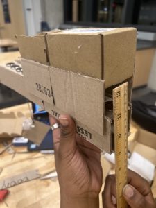
Design Changes:

Spacing between magnets has reduced

The length of the extended sides is larger in hopes of providing more stability

Schedule Changes:

Pushed back prototype 2 design

A was written by Angel Nyaga, B was written by Emanuel Abiye, and C was written by Myles Mwathe


Part A: Global Factors

The product solution meets global factors by providing a user-friendly interface and an educational opportunity to any user, regardless of their country of origin. The user interface in our project will either be a remote or a series of buttons. Both systems will have buttons instructing the track to go from one part of the track to another. While we will provide instructions on how to use the track in English, understanding how the user interface works is not limited to English speakers. Additionally, the electromagnetic principles that can be taught using the remote-controlled maglev train are not limited to English speakers because these lessons are primarily visual. Therefore, our product solution is accessible to a wide variety of individuals of different languages, cultures, and experiential backgrounds.


Part B: Cultural Factors

When it comes to MagLev trains, only three countries have fully implemented them into their transportation systems: China, Japan, and South Korea. Certain factors such as the cost of implementing MagLev trains into their transportation systems, not being able to use the current infrastructure for MagLev trains, etc. play roles in why nations are not looking into implementing MagLev trains into their transportation systems. What we want out of HoverRail is to serve as a learning tool, to show the benefits of MagLev trains. With such knowledge on these kinds of trains as well as seeing the benefits and comparing the pros of MagLev trains with current model trains, we want it to help change the minds of nations and their government or their transportation agency to see how beneficial and more efficient transportation would be in their nation if they replaced current trains with MagLev trains, regardless of cost and not being able to use current infrastructure. We also hope that beyond influencing the opinions of nations, we want it to help influence individuals and their thoughts on MagLev trains. Some people may have never heard of this kind of train and may only be used to the current trains in their nation, and once we introduce HoverRail to such individuals, we hope that we influence their beliefs on transportation, such that these individuals would want to see a fully scaled MagLev train being implemented in their country. There might also be those who are totally against innovating the train systems in their country and may want to stick with the traditional method or stick with the traditional train designs. For these individuals, though it may be hard to fully influence them from their beliefs, we hope that the introduction of HoverRail could spark some sort of dialogue or some contemplation of this new design of trains amongst these individuals, and hopefully to the point where they ease up on their beliefs and become more accepting of innovation and replacing traditional train designs with MagLev trains.


Part C: Environmental Factors

HoverRail does not create much waste leading to low environmental impact. Our MVP will be at most 1-meter long and the carrier will not have a massive size. HoverRail does pose safety concerns when it comes to people wearing conductive materials near the track and carrier. Because of this, warning signs will be provided very clearly with the product. Our product is intended to be durable and reusable. We want electromagnetics students to be able to use HoverRail as a learning tool, and such a tool needs to be durable and readily available multiple times over. HoverRail is not meant to be discarded after a certain amount of uses, the users are meant to keep using the trainset as many times as possible. Lastly, when it comes to the consumption of natural resources as it pertains to HoverRail, we aim to make all of the materials needed to operate our train system easy to attain. We want HoverRail to be easily replicated in classrooms or home environments. Because of this, we avoided the use of obscure materials like Liquid nitrogen which increases the strength of the magnets by dropping the temperature.

Team Status Report for 2/24

Risks:

Stability: We still have some work to do on finalizing the length and other components when it comes to stability, but our whole project focuses on whether the carrier could levitate smoothly while traveling around the track. This poses a huge risk to us and really determines whether or not we can continue making progress on our project, as well as adding a risk to meet our new proposed MVP. When working on the cardboard prototype, we realized that whenever we placed our carrier on the track, the carrier would jump off the track to the side. We kept altering the thicknesses and the length of the sides on the carrier. We looked into increasing the length of the carrier itself which seemed to help out a bit alongside the new lengthened sides. We have also discussed altering the design of the support system on the carrier as well as the actual track itself to allow for more support and canceling any chances of the carrier jumping off as previously stated. If our plans for stability don’t meet our expectations, we can pivot into altering the support portion of the carrier, i.e. having wheels ride along the track instead of lengthened sides.


Propulsion: Another risk we can encounter for this project is making sure our H-Bridge and Arduino work perfectly with each other to allow for propulsion across the track. This system affects the speed of the carrier and whether the carrier would be able to move at all. This poses a huge risk because as previously stated, any failures of the H-Bridge or the Arduino could mean that we would only have a levitating carrier but it wouldn’t be able to move. Of course we could simply push the carrier across the track but we want our product to stand out to the existing market, thus making this an even more important task. We can look into buying alternative H-Bridge chips and Arduinos if the ones we have doesn’t function as expected, but overall we could look into pivoting towards a mechanical wheel system which would implement some sort of battery or motor for the carrier.


Design Changes:

  • Carrier will be redesigned to have a greater length to help with stability when levitating. With a shorter carrier, there were issues with the carrier rotating on its side and slipping off the track. The carrier’s legs will be thicker and filled in and not hollowed out as shown in the design review presentation, the thicker legs will help with sturdiness as the legs broke after 3D printing. 
  • The track will be redesigned to have grooves where the carrier will contact to ensure greater security when the carrier is moving along the track, and make sure the carrier doesn’t lean awkwardly to one side. 
  • With both design changes, the only cost will be extra time allocated for additional CAD design and the actual 3D printing. Cost is not severe enough for mitigations.

Cardboard prototype with levitation

updated schedule