Risks:
With the speed-up coil, the risks that can occur are related to the strength of the magnetic field produced, as well as the timing of activating the coil for the best result for propelling the carrier across the track. When it comes to the strength of the magnetic field, we need to make sure that we maximize the magnetic field produced to be strong enough to push the carrier from one coil to the other. Initial tests with just the carrier as well as cardboard prototypes show encouraging signs that we are able to push the carrier to some capacity, but there is room for improvement, such as increasing turns and radius of these turns, as well as using better AWG for copper wire since we are stuck using 18 AWG which is thicker than the preferred 24 AWG wire since 24 AWG allows for easier and tighter turns, which would only improve magnetic field strength. When it comes to the timing of activating the coil, there is a huge difference in terms of where the carrier is located on the track and the direction in which the carrier is traveling. Based on initial readings, when we program the carrier to travel to the right and the track is positioned from left to right, the propulsion of the carrier is optimized when the back of the carrier is located within the range of halfway of the coil, to the right end of the coil. When we program the carrier to travel to the left, and the track is positioned as mentioned before, the propulsion of the carrier is optimized when the carrier is close to an inch before reaching the right side of the coil, meaning that the magnetic is stronger to the point where it attracts the carrier to pull it towards the coil, and of course with timing the coil to turn on and off, could excel the carrier well past the coil. The timing is crucial not only for optimizing the propulsion of the carrier but also for ensuring stability for the carrier on the track since, due to testing and figuring out the positioning of the carrier based on the coil, there would be occasions where the carrier would do a flip, do a nose dive, etc.
In order for the carrier to move and appropriately respond to stops and obstructions, it must be able to communicate with the speed up coils and the track. This is done through having the arduino on the track communicate with the arduino on the carrier. HC-05 does this through communicating through serial outputs but each arduino has its own unique configurations for serial outputs. Given that the first serial is being used for plotting to the serial plotter or printing values to the serial monitor, this one can not be used. Some arduinos come with other built in serials or require specific serial libraries. Figuring out how to have both arduinos print from serials that can communicate with each other has been a difficult. However, with some more research, we believed we will find the correct serial/serial library
Some of the ultrasonic sensors would switch between two very different values suddenly when it was being tested though the sensor was not being moved. For example, the sensor was switching between 2cm and 800cm at some point. We believe this is a result of a faulty part since the issue disappeared once the sensor was switched out. To monitor this, a LED is set up to light up if an object is a particular distance away and the distance is being printed into the serial monitor for the carrier ardunio.
Design Changes:
A rail was added to the two-to-one CAD design to assist with stability.
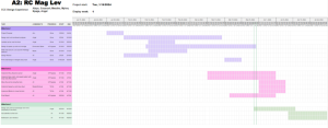
Schedule:
Updated schedule below