Personal Accomplishment:
Mandatory Lab (4 hrs)
- Discuss changes to the track design
- Talk to the Professor and TA to prepare for the demo
Design Research and Self Time (8 hrs)
- Created a new coil (achieving the goal of 200 turns)
- Tested coil with a cardboard prototype
- Start looking into the timing aspect of the coil
Progress:
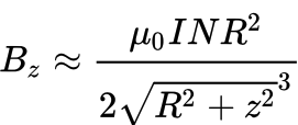
I finally achieved the 200-turn goal I wanted for the speed-up coil. The only issue is that while we were waiting for the 24 AWG Copper Wire to arrive, I had to rely on the 18 AWG Copper Wire, which is thicker. This wire is harder to create turns with, and the coil doesn’t contain the tighter turns that we wanted to have in order to achieve a higher magnetic field. I tested the strength of the coil with just the carrier, and visual confirmation showed that there were much stronger reactions from the carrier when the coil had current running through. I was finally confident enough to test the coil on a cardboard prototype track and carrier system, and the results showed that the carrier would propel but issues such as stability played a role since the carrier would do a nose-dive or fall and lean on one side of the track after being pushed by the coil. This is very encouraging news, but there is still room for improvement, as mentioned. With the anticipated 24 AWG Copper Wire, I anticipate a new coil that would contain a larger radius, more turns, tighter turns, and shorter height of the coil, which would only increase magnetic field production. I am also starting to look into new power supplies even though I am currently satisfied with our current one, but the issue is that the limit in terms of current being fed is 5.1 Amps, and my goal was to feed about 6 Amps through the coil. Of course, from everything mentioned before, from a larger radius, more turns, shorter height of the coil, and more amps using the equation mentioned last week, we are anticipating an even larger magnetic field being produced.

I also started working on the timing aspect of the coil, when to activate it, and when to shut it off to optimize the distance traveled once the coil pushes the carrier. Initial testing showed different results depending on the carrier’s location on the track and its traveling direction. When the carrier was traveling to the right, I saw that it was best to activate the coil when the back of the carrier was within the range from the middle of the coil to the right end of the coil. When the carrier was traveling to the left, I saw that it was best to activate the coil when the carrier was around an inch before reaching the right end of the coil. I also played with the pulse width modulation of the current through the H-Bridge into the coil and saw that lowering the PWM resulted in a stronger reaction from the carrier to the coil.
Schedule:
We are on schedule because we are waiting for the actual carrier’s printing to see the results of the new solenoid we created.
Next Week’s Schedule:
Implement the new coil on the 3D-printed track to test the actual results of our carrier. If the results are the same and we are not creating a strong enough magnetic field to propel the carrier, we will create a new solenoid that would implement tighter turns and a larger radius for the coil turns since we are still waiting for the 24 AWG Copper Wire. We will also apply a new power supply to feed 6 Amps to create a stronger speed-up coil. Since we can now work with Bluetooth, I want to be able to properly receive signals from the carrier to see what I can do with such signals, such as cutting off current or applying current to the coil.
