
- Mandatory Meeting (4hr)
- Discuss design changes for the track
- Go over feedback from design review
- Independent Work (8hr)
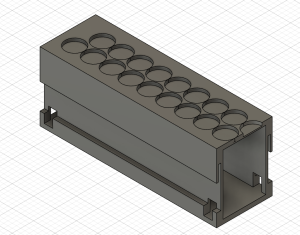
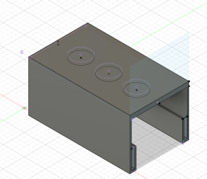
- 3D print two-to-one track with rail and smaller carrer
- Work with two linear hall effect sensors to solidify
- Work with ultrasonic sensor
- Updated block diagram
This week, I worked on printing initial versions of our final track. Since the two-to-one track/carrier magnet prototype was more stable, this is the design that was printed. The printed track is 1/5 of our final design, making it 20 cm long. The width is 6.5 cm to be able to hold speed up coils with an approx. diameter of 6 cm. The height is 7 cm to have enough room to support the track and levitate the carrier an inch (2.54 cm). The size of the carrier was reduced to reduce cost and to give easy access to the circuit that will be placed above the carrier.
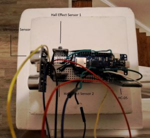
I also worked on testing the two magnetometers as stops for the track. To do this, I connected three LEDs to the Arduino that would light up depending on what was in front of the magnetometers. The yellow LED would light up if there was no magnets in front of either magnetometer. The red LED lights up if there is a negatively charged magnet next to either magnetometer. The green LED lights up there is a positively charged magnet next to either magnetometer. This will be used to help debug stops along the track, something that will be controlled through wireless communication between the track and carrier Arduino. We expect this step to be complex so this circuit will helpful through the process
I also worked on the ultrasonic sensor. The ultrasonic sensor is suppose to stop the carrier if something is within 10 cm of the track. This requires wireless communication, something we have not solidified. To test this at the moment, I am using a red LED that lights up if something is within 10 cm of the carrier breadboard.
I also begin working on the HC-05 wireless communication. Given that we are still working on our speed up coils, I am testing this with a separate Arduino uno and the Arduino MKZero on the carrier. I am in the process of debugging the code for the “receiver”, or the arduino uno. For the wireless communication, the carrier, (if it sees a stop or an obstruction) sends information to the track (to slow down/speed up the track depending on the case). For the HC-05, this done through writing and reading different serial outputs. Each arduino has different ways of reading/writing to a serial. I am in the process of debugging the serial for the Arduino Uno. The serial I used in the MKZero is not accessible for the Arduino Uno.
Breadboard for the carrier
Next Week
I plan to further debug wireless communication so we can test how the track arduino and carrier arduino will communicate. Also, I want to work on design how the magnets will be placed along the track to make a stop,