Emanuel’s Status Report for 3/30

Personal Accomplishment:

Mandatory Lab (4 hrs)

  • Discuss changes to the track design
  • Talk to the Professor and TA to prepare for the demo

Design Research and Self Time (8 hrs)

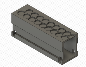
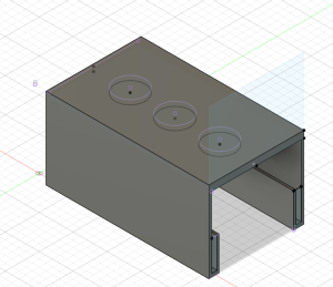
  • Created a new coil (achieving the goal of 200 turns)
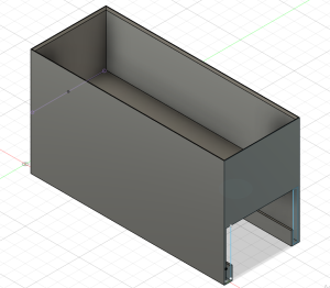
  • Tested coil with a cardboard prototype
  • Start looking into the timing aspect of the coil

Progress:

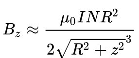
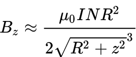
I finally achieved the 200-turn goal I wanted for the speed-up coil. The only issue is that while we were waiting for the 24 AWG Copper Wire to arrive, I had to rely on the 18 AWG Copper Wire, which is thicker. This wire is harder to create turns with, and the coil doesn’t contain the tighter turns that we wanted to have in order to achieve a higher magnetic field. I tested the strength of the coil with just the carrier, and visual confirmation showed that there were much stronger reactions from the carrier when the coil had current running through. I was finally confident enough to test the coil on a cardboard prototype track and carrier system, and the results showed that the carrier would propel but issues such as stability played a role since the carrier would do a nose-dive or fall and lean on one side of the track after being pushed by the coil. This is very encouraging news, but there is still room for improvement, as mentioned. With the anticipated 24 AWG Copper Wire, I anticipate a new coil that would contain a larger radius, more turns, tighter turns, and shorter height of the coil, which would only increase magnetic field production. I am also starting to look into new power supplies even though I am currently satisfied with our current one, but the issue is that the limit in terms of current being fed is 5.1 Amps, and my goal was to feed about 6 Amps through the coil. Of course, from everything mentioned before, from a larger radius, more turns, shorter height of the coil, and more amps using the equation mentioned last week, we are anticipating an even larger magnetic field being produced.


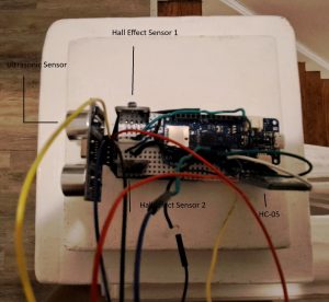
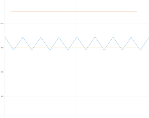
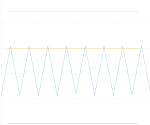
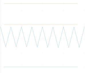
I also started working on the timing aspect of the coil, when to activate it, and when to shut it off to optimize the distance traveled once the coil pushes the carrier. Initial testing showed different results depending on the carrier’s location on the track and its traveling direction. When the carrier was traveling to the right, I saw that it was best to activate the coil when the back of the carrier was within the range from the middle of the coil to the right end of the coil. When the carrier was traveling to the left, I saw that it was best to activate the coil when the carrier was around an inch before reaching the right end of the coil. I also played with the pulse width modulation of the current through the H-Bridge into the coil and saw that lowering the PWM resulted in a stronger reaction from the carrier to the coil.
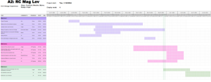
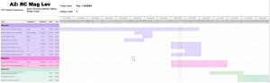
Schedule:

We are on schedule because we are waiting for the actual carrier’s printing to see the results of the new solenoid we created.

Next Week’s Schedule:

Implement the new coil on the 3D-printed track to test the actual results of our carrier. If the results are the same and we are not creating a strong enough magnetic field to propel the carrier, we will create a new solenoid that would implement tighter turns and a larger radius for the coil turns since we are still waiting for the 24 AWG Copper Wire. We will also apply a new power supply to feed 6 Amps to create a stronger speed-up coil. Since we can now work with Bluetooth, I want to be able to properly receive signals from the carrier to see what I can do with such signals, such as cutting off current or applying current to the coil.

Myles’s Status Report for 3/30

Personal Accomplishments:

  • Lab Meetings (4 hrs ):
    • Met with Professor and TA to discuss expectations for interim demo
    • Discussed with teammates delegation of work with interim demo
  • Indiviudual Work (8 hrs):
    • Created a working demo for h-bridge circuitry
    • Did a run thru of the interim demo with teammates

Progress:

This week my main accomplishment was setting up a demo for the h-bridge component. The goal of my demonstration is to show that we can programmatically control the polarity of the current going through our coils using a microcontroller. The way I will demonstrate by alternating the spinning direction of a miniature propeller that I have. The alternate spinning is meant to show the different directions we can make the current go, with the help of the h-bridge. Going into next week I hope to make progress with our Bluetooth components to enable communication between our subsystems. Mainly Bluetooth communication will allow the carrier to send its magnetometer signals to the track to activate the coils and allow current to pass through the coils. I will be passing off the work of the coil design and time aspect of the activation of the speed coils to Emmanuel and will about the programming aspects when it comes to the microcontroller.

Next Week Deliverables:

  1. Simple Bluetooth demonstration communication between the Arduino Nano and Arduino UNO

Team Status Report for 3/30

Risks:

With the speed-up coil, the risks that can occur are related to the strength of the magnetic field produced, as well as the timing of activating the coil for the best result for propelling the carrier across the track. When it comes to the strength of the magnetic field, we need to make sure that we maximize the magnetic field produced to be strong enough to push the carrier from one coil to the other. Initial tests with just the carrier as well as cardboard prototypes show encouraging signs that we are able to push the carrier to some capacity, but there is room for improvement, such as increasing turns and radius of these turns, as well as using better AWG for copper wire since we are stuck using 18 AWG which is thicker than the preferred 24 AWG wire since 24 AWG allows for easier and tighter turns, which would only improve magnetic field strength. When it comes to the timing of activating the coil, there is a huge difference in terms of where the carrier is located on the track and the direction in which the carrier is traveling. Based on initial readings, when we program the carrier to travel to the right and the track is positioned from left to right, the propulsion of the carrier is optimized when the back of the carrier is located within the range of halfway of the coil, to the right end of the coil. When we program the carrier to travel to the left, and the track is positioned as mentioned before, the propulsion of the carrier is optimized when the carrier is close to an inch before reaching the right side of the coil, meaning that the magnetic is stronger to the point where it attracts the carrier to pull it towards the coil, and of course with timing the coil to turn on and off, could excel the carrier well past the coil. The timing is crucial not only for optimizing the propulsion of the carrier but also for ensuring stability for the carrier on the track since, due to testing and figuring out the positioning of the carrier based on the coil, there would be occasions where the carrier would do a flip, do a nose dive, etc.

In order for the carrier to move and appropriately respond to stops and obstructions, it must be able to communicate with the speed up coils and the track. This is done through having the arduino on the track communicate with the arduino on the carrier. HC-05 does this through communicating through serial outputs but each arduino has its own unique configurations for serial outputs. Given that the first serial is being used for plotting to the serial plotter or printing values to the serial monitor, this one can not be used. Some arduinos come with other built in serials or require specific serial libraries. Figuring out how to have both arduinos print from serials that can communicate with each other has been a difficult. However, with some more research, we believed we will find the correct serial/serial library

Some of the ultrasonic sensors would switch between two very different values suddenly when it was being tested though the sensor was not being moved. For example, the sensor was switching between 2cm and 800cm at some point.  We believe this is a result of a faulty part since the issue disappeared once the sensor was switched out. To monitor this, a LED is set up to light up if an object is a particular distance away and the distance is being printed into the serial monitor for the carrier ardunio.

Design Changes:

A rail was added to the two-to-one CAD design to assist with stability.

Schedule:

Updated schedule below


Angel’s Status Report for 3/30

  • Mandatory Meeting (4hr)
    • Discuss design changes for the track
    • Go over feedback from design review
  • Independent Work (8hr)
    • 3D print two-to-one track with rail and smaller carrer
    • Work with two linear hall effect sensors to solidify
    • Work with ultrasonic sensor
    • Updated block diagram


This week, I worked on printing initial versions of our final track. Since the two-to-one track/carrier magnet prototype was more stable, this is the design that was printed. The printed track is 1/5 of our final design, making it 20 cm long. The width is 6.5 cm to be able to hold speed up coils with an approx. diameter of 6 cm. The height is 7 cm to have enough room to support the track and levitate the carrier an inch (2.54 cm). The size of the carrier was reduced to reduce cost and to give easy access to the circuit that will be placed above the carrier.

I also worked on testing the two magnetometers as stops for the track. To do this, I connected three LEDs to the Arduino that would light up depending on what was in front of the magnetometers. The yellow LED would light up if there was no magnets in front of either magnetometer. The red LED lights up if there is a negatively charged magnet next to either magnetometer. The green LED lights up there is a positively charged magnet next to either magnetometer. This will be used to help debug stops along the track, something that will be controlled through wireless communication between the track and carrier Arduino. We expect this step to be complex so this circuit will helpful through the process

I also worked on the ultrasonic sensor. The ultrasonic sensor is suppose to stop the carrier if something is within 10 cm of the track. This requires wireless communication, something we have not solidified. To test this at the moment, I am using a red LED that lights up if something is within 10 cm of the carrier breadboard.

I also begin working on the HC-05 wireless communication. Given that we are still working on our speed up coils, I am testing this with a separate Arduino uno and the Arduino MKZero on the carrier. I am in the process of debugging the code for the “receiver”, or the arduino uno. For the wireless communication, the carrier, (if it sees a stop or an obstruction) sends information to the track (to slow down/speed up the track depending on the case). For the HC-05, this done through writing and reading different serial outputs. Each arduino has different ways of reading/writing to a serial. I am in the process of debugging the serial for the Arduino Uno. The serial I used in the MKZero is not accessible for the Arduino Uno.

Breadboard for the carrier

Next Week

I plan to further debug wireless communication so we can test how the track arduino and carrier arduino will communicate. Also, I want to work on design how the magnets will be placed along the track to make a stop,

Team Status Report for 3/23

Risks

One major risk for our project is the speed-up coils. While working on the solenoids, we realized that we didn’t produce enough magnetic field to propel our carrier. We confirmed with testing with a singular magnet that the magnetic field we have produced is strong enough to propel the magnet, but the goal of these coils is to propel the carrier across the track. We have made changes to our solenoid such as changing the radius, changing the amount of turn, and  the location of the solenoids on the track. We calculated that we produced a stronger magnetic field but have also run into the same issue of not being able to propel the carrier. This poses some risk for our project since the MVP heavily relies on being able to move the carrier along the meter long track.


Another risk for our project is the stability of our carrier. The stability of our carrier is determined by the ratio and of magnets along the track and carrier and the design of the track and carrier. We started working on the two-to-one track design due to issues with stability in the one-to-one option. While this was slightly more stable, we noticed that magnets would get stuck in gaps in between groups of magnets. The stability of the carrier on the track affects the ability for the whole maglev train to be successful.


Design Changes:

We have decided to make multiple changes to our solenoids such as increasing the radius of the turns, the location of the solenoid on the track, etc. in order to help produce a stronger magnetic field to propel the carrier. We found out that using the casing of the 24 AWG Copper Wire allows for a larger radius for the turns as well as more stable and tighter turns, thus helping out in producing a larger magnetic field.


We have ordered rectangular magnets. They will be an alternative to the two-to-one circle magnet track with less possibility of magnets getting stuck do to their being no major gaps between the magnets (they create a straight line).

We have a CAD design with a guide way for the track. This would limit the movement of the track, decreasing the chances that the track would flip over.


Schedule Change:

We are on schedule


Angel’s Status Report for 3/23

  • Ethics Meeting (2hr)
    • Discusses Ethics of our project with class
  • Independent Work (10hr)
    • Construct cardboard model of two-to-one carrier/track magnets design
    • CAD design for one-to-one carrier/track circle magnets design
    • CAD design for two-to-one carrier/track circle magnets design
    • CAD design for two-to-one carrier/track rectangle magnets design
    • Determined a way to distinguish stops with a magnetometer


Through out this week, I worked on solidifying the dimensions for the one-to-one track/carrier magnet design and the two-to-one track/carrier magnet design. The main changes to models involved spacing out the magnets on the carrier for the two to one magnet. This mainly do to not having enough magnets when I constructed the cardboard prototype but this design was significantly more stable than the one-to-one design but also levitated higher. However, there were still some issues with the magnets getting stuck in between gaps in the track. This was a large reason why we decided to order rectangular magnets


I also constructed CAD models for the different designs. For track designs, I created  the  one-to-one track circle magnet design, the two-to-one track/carrier circle magnet design, and the track design for the two-to-one track/carrier rectangle magnets system(pictures below). The circle magnet designs are based of the finalized dimensions from the cardboard prototypes. Since the rectangle magnets have not come in yet, this design was based off of predicted behavior based on what we have seen with the circle magnets and the dimensions of the rectangle magnets. One major consideration for the rectangular design is how to orient the magnets. Currently, the longer side of the rectangle is along the track and  there is large gap between the lines of magnets. While the magnets are less likely to get stuck since it is a straightaway, sudden movement in the carrier could result in sides of the magnets getting stuck like in past designs. I would like to create a cardboard prototype of this structure then edit the current CAD design based on the results.

One-to-one track/carrier circle magnets

Two-to-one track/carrier circle magnets

Two-to-one track/carrier rectangle magnet (2mm between lines)

Two-to-one track/carrier rectangle magnet (10mm between lines)

Carrier

Bottom of Carrier

I also created  a derivative of the one-to-one design with a guiding rail for the carrier. This would be in place to help with the stability. This was difficult to construct with cardboard so I would like to print this soon to see if the dimensions of the rail properly account for the height of levitation and sudden movements with the carrier.

One-to-one guided design

Side of one-to-one guided design

Carrier guided design

Side of carrier guided design

I also worked with magnetometers to attempt to make a stop start system. This was done  though attaching two magnetometers to face opposite sides of a breadboard to simulate the sides of the carrier. I tested how the plot changed as I moved magnets along both sides and switched their polarity while adjusting the sensitivity of the magnetometers. Following a few tests, I noticed that the amplitude of the signal on the plot changed based on the polarity of the magnets, the amount of magnets, and the magnetometer the magnets was in front of.  Based of this, I think a baseline signal can be created and significant changes in either side of the signal can represent a stop.

No Magnet near either magnetometer

Negative polarity near magnetometer 1


Negativity polarity near magnetometer 2

Next Week

Next week, I would like to work on making more carrier designs.  Also, I would like to print some portion of all the above designs to see if there are any major design issues I missed. I would also like to continue working with the magnetometer and start working with the ultrasonic sensors to make a full start, stop system.

Emanuel’s Status Report for 3/23

Personal Accomplishment:

Mandatory Lab (2 hrs)

  • Ethics Lecture
  • Discussed ethical components regarding our project and other projects

Design Research and Self Time (8 hrs)

  • Worked with Myles on creating multiple versions of propelling coils
  • Researched proper formula for magnetic field production, ran calculations on our coils
  • Worked on ethics assignments to prepare for the ethics lecture

Absent: (Travelled to NSBE National Conference)

Progress:

With our first solenoid, we discussed our findings with the professor and our concerns that we were not producing enough magnetic field to propel our carrier across our track. After clarification with the professor, we mentioned the multiple missing components we forgot to implement in our calculations, such as the distance of the supporting bolt along the axis, and the change of magnetic field from the corner of the bolt compared to the outside of the coil. We were pointed to this formula:

And used this formula to calculate the magnetic field we produced with our current coil. We also took some pointers from the professor to create a new solenoid. We implemented a new solenoid with a larger radius for the turns of the wire, the distance of the supporting plastic cast along the axis, and placed the coil above the track compared to underneath the track. We ran calculations under the new conditions of our solenoid to confirm that it produced a larger magnetic field than the previous coil. We also ran tests on a single magnet and visually saw how much stronger the magnetic field had an effect on the magnet, and decided to create an even smaller carrier that doesn’t rely on levitation to see whether or not it would propel the carrier. We were able to confirm that the smaller version of the carrier was able to propel in both directions, which only helps to confirm a portion of the MVP, which is to have the carrier properly propel along the meter-long track in both directions.

Schedule:

We are on schedule because we are waiting for the actual carrier’s printing to see the results of the new solenoid we created.

Next Week’s Schedule:

Implement the new solenoids to the 3D-printed track to test the actual results of our carrier. If the results are the same and we are not creating a strong enough magnetic field to propel the carrier, we will create a new solenoid that would implement more turns and a larger radius for the coil turns since we plan on buying a new 24 AWG Copper Wire.

Myles’s Status Report for 3/26

Personal Accomplishments:

  • Lab Meetings (2 hrs, traveled to NSBE National Conference ):
    • Met with class to discuss ethical considerations of our project
  • Indiviudual Work (8 hrs):
    • Reworked the design of propelling coils to generate more magnetic strength
    • Worked on ethics assignment, to prepare for discussion on ethics day

Progress:

This week the main issue I worked on with Emanuel was making our solenoids stronger and generating more force to push our carrier forward. As I mentioned last week I was initially confused about our calculations as we were generating a lot of magnetic field strength but our results were not reflective of this. What I hadn’t realized was that I was using the wrong equation when it came to doing calculations in our case. We should have been using the short solenoid estimate version of the equation found here. With this equation, we were able to realize that our initial calculations referred to the magnetic field with the center of the solenoid where the steel core was not outside or near the solenoid. In reality, there should have been a factor of the equation accounting for how far the carrier was from the solenoid itself. This same equation had a radius factor, so making our solenoid wider, would make the solenoid more effective. We are also considering lessening our levitation required to make the z factor in the equation less in order to give us even more force. In our case, we find that we had too much levitation as opposed to too little. Going into next week, I would like to attach our improved coils to our printed track and see what design changes need to be made before our demo.

Next Week Deliverables:

  1.  Attach coils to printed track
  2. Create more wider coils

Emanuel’s Status Report for 3/16

Mandatory Lab (4 hr.)

  • Met with professor and TA to discuss recent design report
  • Discussed with the team about work distribution

Design Research and Self-Time (8 hr.)

  • Worked on the speed-up coil
  • Looked more into how to interpret readings from Linear Hall Effect Sensor
    • Readings from a magnet depending on distance
    • Readings from speed-up coils

Progress:

We started looking into how to interpret the readings from the Linear Hall Effect. At first, we had difficulty interpreting the data, but a discussion with the professor cleared up the confusion. I then wanted to see what the fixated readings from a single magnet look like depending on how far the magnet is from the sensor. At first, when looking at the readings from the magnet with the professor, I was confused about why the readings were decreasing, as they should have increased from the normal base rate of 510, indicating no magnetic field. However, after further research, I learned that it depends on the polarity or the side of the magnet facing the sensor. So, for my individual research with the sensor, I made sure to collect data from both sides of the magnets. The following are the data that I collected:

Linear Hall Effects Readings:

(Same polarity)

3 inches away: 511

2 inches away: 514

1 inches away: 534

.5 inches away: 600

.25 inches away: 745

(Opposite polarity)

3 inches away: 509

2 inches away: 507

1 inches away: 491

.5 inches away: 416

.25 inches away: 284

From this, it’s clear to see that we need to take distance into account if we want to get a clear, distinct change in magnetic field readings when the carrier is running on the track when the carrier is approaching a speed-up coil, etc.

I also worked with Myles on improving the speed-up coil since, for some reason, it decided to no longer work from the first time I created them. We made two new designs for the solenoids with different turns and lengths. We also made sure to find the calculations of these solenoids and share them with the professor and the TA to make sure we were approaching this correctly. After consulting with the professor and clarifying measurement and data, we realized that we were not generating as much magnetic field as we actually anticipated, and we needed to look into incorporating new coil designs.

Schedule:

Since we recently changed our schedule, we are currently on track with the new schedule.

Next Week’s Schedule:

Create new solenoid coils with stronger magnetic field output and implement them into the track to test propulsion with the carrier. Since Myles and I are away at the NSBE National Convention, we will put our complete effort into finalizing these coils. The only thing left for our group is finalizing the track and carrier design and finally printing them.

Team Status Report for 3/16

Risks

One major risk in our project currently is interpreting data retrieved by the linear hall effect sensor. While this device met our specification needs, it is very sensitive to close-range changes in magnetic field. For example, moving a magnet across the magnetometer will cause high peaks and lows on the graph produced by our Arduino, signifying great changes in the magnet field. However, moving a far magnet across the magnetometer produces little change in the magnet field. This behavior will force us to do extensive signal processing to interpret the magnetometer data so we can 1) establish a baseline sinusoidal for when the carrier is regularly moving along the track and 2) properly detect peaks in the magnetometer from the speed coils or approaching a stop (another magnet).

Another risk comes from creating a stable carrier. Currently, the prototype for the one-to-one carrier and track magnet design levitates but is sensitive to sudden movement, even when the sides of the track are elongated. Given we have not tested this design with our speed up coils, this can cause some problems once the train starts to move. We were previously given a design suggestion from course staff that have attempted to implement. This design involved a one-to-two carrier and track magnet design. However, due to gaps between magnets in the track, the sides of the carrier magnets would be attracted to the sides of the track magnets due to the gaps in track. Given that the magnets are circular, we could not come up with a solution to this problem without considering buying smaller magnets to but in these gaps or using new, straight magnets instead.


We found with our current propelling coils that we are not generating as much force as we would have expected. We need to make sure that we have the coils as close to the carrier as possible to ensure the magnetic field is at its strongest. We also will look to replace the bolt in the middle of the coil with a plastic core to reduce the inductance of the solenoid so that we do not need to drive as much voltage to our bridge. 

Design Changes:

Spacing between the magnets has further reduced in the straight-away one-to-one design to 0.5 cm between each magnet in the track and carrier. Spacing for the straight away two-to-one design has changed from 1cm to 0.5cm to no space. Given the problems with this design, we expect to see more changes in the following week. Make our propelling coils larger in hopes of creating larger magnetic field strength, and replacing the steel core with a plastic or somehow an air core. 

Schedule Change:

We have changed our schedule to be more accurate to our current design, responsibilities, and progress on those responsibilities.