Progress
This week I implemented the Faraday’s law experiment using the components we purchased.
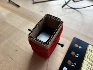
As the figure below shows, I glued two ceramic magnets onto a bolt, and placed the magnets inside an inductor coil wound with magnet wire around a frame made of cardboard. The poles of the magnets are located at the large top and bottom surfaces, so the magnetic flux in the coil changes as the bolt is rotated, inducing an emf. The two ends of the coil are then connected to an oscilloscope and a red LED, which is used as a visual indicator of the strength of the induced emf.
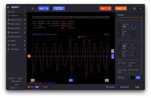
The plot below shows the time-varying induced electromotive force. Note that each vertical division represents 500 mV, so the peak voltage induced is about 2V, which is higher than the turn on voltage of a red LED, and it indeed lit up.
I believe I am still on schedule, as I completed the tasks outlined in last week’s report.
Plan for next week
I think it will be interesting to connect another LED that is in the opposite direction as the first one to the coil to see if they alternate lighting up (which should be the case) next week. Additionally, I will try to learn to use the laser cutters in TechSpark and cut a nicer frame for the experiment after I polish the design.