Shizhen’s Status Report for April 29

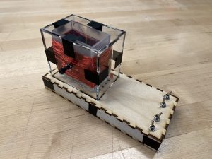
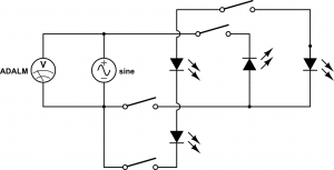
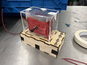
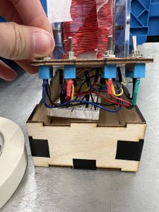
This week I made some modifications to the case of the Faraday’s law experiment. Specifically I increased the height of the base to accommodate the wires that connect the switches and the LEDs. I also made the length of the base shorter to save some material, since I decided to replace the full-size breadboard with the half-size breadboard. I then laser cut the case and wired up the switches and the LEDs to the emf generator according to the wiring diagram and the circuit schematic below.

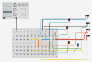
The completed experiment set-up is shown below. Different combinations of LEDs will light are when the magnets are spun, according to the states of the switches.

Wiring in the base

I also worked with Mudit to create a laser-cut design for the case of the Ampere’s law experiment, which will be fabricated in the next few days, if not this weekend. Finally, I worked with Aaron and Mudit to make sure the web application can support measuring with two oscilloscope channels and displaying the plots.

Overall I am on schedule. In the last week leading up to the final demo, I will touch up the experiment set-ups to make them look better. I will also work on the educational content, in addition to the final report and video.

Aaron’s Status Report for April 29

This week, I continued development of the web application and continue to prepare for the final demo. I worked on implementing the gamified quiz and added implementation of a leaderboard for the quiz and scores based on how long the quiz took to take. I also continued testing the content of the web application with different age ranges and added improved front end features and drop down menus to navigate between the website easier according to user feedback. I also designed a logo for the webpage and made the theme of the website more consistent, sleek and professional. I am on schedule and will work on polishing the web app to its finished state in the next week and a half before the final demo and work on the final report, posters, and videos.

Team Status Report for April 29

At this point, our project is essentially completed as we have our experiments finalized and integration has been tested. There is no major risk that could jeopardize the completion of our project.

No changes were made to the design or schedule for our project.

Validation and Verification

  1. We first tested the accuracy of our voltage readings. We did that by comparing the maximum peak to peak voltage recorded in Scopy to the voltages recorded on the web app via the ADALM. We were within our passing criteria of a maximum 3% error rate. This was expected as the ADALM oscilloscopes are very accurate themselves.
  2. To ensure low latency for the web app animation update when we make a change to the physical circuit, we timed the time between when the crank is first turned to when the web app updates its graph, and we were within our passing criteria of a maximum 1 second latency. We therefore, did not need to change our design after this test either.
  3. To test the repeatability and reusability, we wanted to ensure the circuits last for around a 1000 attempts (any physical change made to the circuit). We tested that with the help of a power drill running continuously for around 1.5 to 2 minutes as shown in the final presentation. That helped ensure our experiment could last for long periods of repeated usage. For the Ampere’s law experiment, we essentially used the ADALM signal generator to produce an AC signal for the solenoid that would continuously deflect the compass to ensure it lasted for many rounds of battery polarity changes. Both the experiments passed the tests, ensuring our design is robust.
  4. Rotated magnets in the Faraday’s law experiment by hand and used an oscilloscope to measure the induced emf. A Vpp of 4.54 V was achieved at 6.65 Hz, which is higher than the turn on voltage of an LED. The induced emf was able to turn on two red LEDs in series, and a red and a blue LED in parallel.
  5. Measured the current through the Ampere’s law experiment to be around 2 A. The induced magnetic field strength is approximated to be 5.7 mT with Ampere’s law, which was able to deflect the needle of the compass significantly (~180 degrees).

Mudit’s Status Report for April 29

This week I worked on rehearsals for the final presentation, completing the poster that is due next week and drawing up designs for the Ampere-Maxwell Experiment Box similar to the one for the Faraday’s Experiment. I also worked with Aaron on testing the voltage readings from the Amp-Max Experiment as recorded on the web app via the ADALM.

My progress is on schedule and in the next week, I’ll mostly be working on the Final Report and making the Video submission for the project, while assisting Shizhen in printing and finalizing the Ampere-Maxwell Box.

Aaron’s Status Report for April 22

This week I worked on integration of the Ampere Maxwell experiment with the web application, worked on development of gamified quiz components, updated the front end of the web application, and tested the web application with other college level students and received feedback on the modules.

Similar to the integration of the Faraday’s law experiment with the web app, we used ADALM and libm2k to send the measured voltage to the web app. After running into some bugs, Shizhen figured out that  AC coupling was selected on the BNC adapter for the oscilloscope (which is why the DC component was not present), and we were able to display the plot on the web application.

I then worked on implementation of the quiz questions, and created a new model for the quiz. I will time the amount of time the quiz takes on each question, and also score based on correctness. I also created a leaderboard model that stores usernames and the score they have received on the quiz. I am still working on some bugs in the implementation and will work next week to catch up on it.

I believe I am on track. This weekend I will work on fixing the bugs, and will also continue to update the front end of the web app before the presentation next week. Next week I will continue development of the web app and polishing final features.

Shizhen’s Status Report for April 22

This week I worked on the final presentation and the content of the modules, made the cases for the two experiments, and along with Mudit and Aaron, integrated the Ampere’s law experiment with the web application. For the final presentation, I updated the block diagrams and contributed to the verification and validation sections. I also edited the content of the intermediate level module and added 8 questions to the quiz.

Similar to the integration of the Faraday’s law experiment with the web app, we used ADALM and libm2k to transmit the measured voltage across the solenoid in the Ampere’s law experiment to the web app. Initially we were perplexed because we were only able to observe the transient response of the circuit — the voltage rises when the direction of current is switched, and quickly drops to 0. After realizing that AC coupling was selected on the BNC adapter for the oscilloscope (which is why the DC component was not present), we were able to display the desired plot on the web app.

To fabricate the cases for the experiments, I first came up with a few designs and shared with my teammates to get their feedback. The main design tradeoffs that I considered were whether to enclose the LEDs in the Faraday’s law experiment, and whether to show the breadboard used to make electrical connections. Ultimately, we decided that the LEDs should be enclosed so that users cannot remove them; and that the breadboard should be hidden to avoid confusing people who do not know the internal workings of a breadboard. After sketching the case on paper, I made a 3D drawing of it in TinkerCAD. Then I used CoralDraw to generate the drawing to be laser cut. Initially, the kerf setting for the parts was a little off, so the boxes fit too tightly, but overall the case satisfies our needs.

Faraday’s law experiment with case

I believe I am on track. This weekend I will try to find the optimal kerf value through trial and error, and finalize the case for the Faraday’s law experiment. Next week, I plan to make the case for the Ampere’s law experiment, and work on the educational content.


Mudit’s Status Report for April 22

Over the past two weeks, I worked on confirming the design for the Ampere-Maxwell Experiment and buying the required items like galvanometer. I also developed the EM web app educational content for the Basic and Advanced levels, as well as the quiz questions for those two levels. This week I mostly worked on building the final presentation deck that I will be presenting next week.

My progress is on schedule and in the next week, I will work with Shizhen on setting our experiment circuits in the cases for the final demo, while also beginning work on the poster and report.

Team Status Report for April 22

Currently, the most significant risk that can jeopardize the success of the project is not having high quality educational content for the web application. Ultimately, our project aims to educate and inspire people about electromagnetism. However, people will not learn as much if the educational content is unclear, boring, or too easy/too difficult, even if the experiments work perfectly and the integration is seamless. Therefore, to mitigate this risk and make the content more instructive, all three of us will proofread and edit the modules for the three different difficulty levels. We will also try to have friends and family to read the modules and provide feedback. Additionally, we will solicit advice from people with expertise in electromagnetism on how to present the concepts intuitively if we have trouble explaining certain points clearly. We can also refer to old lecture slides, notes, and recordings to confirm our explanations.

No changes have been made to the design and implementation of our project, and our schedule remains the same.

Aaron’s Status Report for April 8

This week I worked on the integration of the Faraday’s law experiment and the web application. I worked with Shizhen to install and debug libm2k, which was not previously working. After some debugging, we were able to use ADALM’s oscilloscopes directly with a Python script. Shizhen and I then worked to parse the data from the scopy in real time, which uses both a script that uses a libm2k to process information from the ADALM, writing the info into a csv file. Then the CSV file is read from a Django views function called by the web app, so the data can be updated in real time.

I also worked with Shizhen to display the oscilloscope plots on the web app in real time, where we faced some challenges related to the smoothness of the animation, and we will continue to work on it next week.

Additionally, I spent some time polishing the web application. I debugged the exercises feature, and got exercises successfully working. I also made some user interface adjustments and functionality. Then, I updated the modules using the Educational Modules written up by Mudit before the demo.

I am pleased with our progress overall, and believe we are soon able to reach MVP. Next week I will work on smoothing out the animation from the display, and also integrate the web application with Mudit’s Ampere-Maxwell experiment. Then, I will see if I can add additional features to the web oscilloscope, such as adjusting the period. I will also add multiple difficulty levels for the educational modules to reach a wider audience.

For testing, we will ask Professor Chamanzar about what additional features can be added to the web application to aid E and M education, and will ask users with varying levels to test the web application and integrate their feedback. I will also work with some of my peers that have more experience with front end UX design to see how our web page can be made more professional, interactive and user friendly.

Shizhen’s Status Report for April 8

This week I primarily worked on the integration of the Faraday’s law experiment and the web application. Because last week I was not able to install libm2k (a C++ library that interfaces with ADALM) and its Python bindings on my Mac laptop, I worked with Aaron to see if his Windows computer would support the library. I shared with him my findings, and we were able to successfully install libm2k and control an ADALM’s oscilloscopes directly with a Python script. We realized that the noise was significant in the data, so I employed the Butterworth digital lowpass from SciPy to filter out the noise. The original (red) and filtered signal (blue) are displayed below.

I also worked with Aaron to display the oscilloscope plots on the web app in real time, where we faced some challenges related to the smoothness of the animation, and we will continue to work on it next week. If this problem persists, we will look into other ways to display the oscilloscope plots, such as using Scopy.

I also started designing the final version of the Faraday’s experiment, and will purchase and laser cut a few more parts, and fabricate the system next week. Overall, I believe I am on schedule, as last week’s challenge with using libm2k was solved.

Testing and Validation

The following is a list of tests that I have or will run along with the analyses for the results.

  • Used a power drill to spin the magnets in the Faraday’s law experiment at a very high rate and induced a peak-to-peak voltage of about 16V to see if the LEDs would blow out. Observed that the LEDs used continued to function normally, so in regular use-cases the LEDs should not pose any danger to the user.
  • Inspect the final experiments to ensure there are no sharp edges, corners that can be dangerous.
  • Use the experiment under different scenarios (applying varying forces, performing unintended behaviors, etc) and repeatedly to ensure it’s robust.
  • Proofread the content of the educational modules and let other people with different levels of experience in physics to use the modules to test the modules’ effectiveness and clearness.
  • Measure the delay between action performed in the experiment and the response of the web application to see if the delay is within the limit we set forth.
  • Measure the induced AC voltage with Scopy and compare the result with our measured results to see if the measurements are accurate.