
This week I primarily worked on testing the Faraday’s law experiment and the Arduino MKR 1010 Wi-Fi board.
Faraday’s Law Experiment
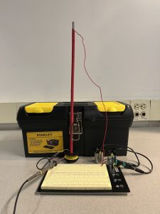
Since I do not have a magnet yet, I constructed an electromagnet by winding wire around a thin, long metal rod, which is somewhat ferromagnetic. I then shorted the wire with two 9V batteries connected in series, and the current was measured to be about 2.00 A. I then put an “induction coil” (a spool of wire) through the electromagnet, and connected two ends of the coil to an oscilloscope to measure the induced electromotive force. The set-up is shown in the image below.
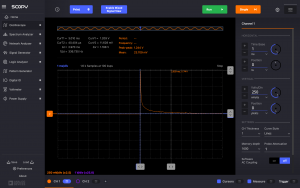
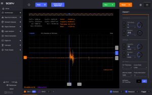
When the power supply is turned on or off, an appreciable amount of voltage (~1V) change can be observed, but it decays very quickly, decreasing to almost 0V in less than 5ms. Additionally, moving the induction coil induces a small voltage (~100mV), and it is also quite transient. Some oscilloscope graphs are shown below. Therefore, it appears relying on linear motion cannot generate the required voltage to turn on an LED, which is deemed an important visual aspect of the demonstration.
Arduino MKR 1010 Wi-Fi
I tested the Arduino MKR 1010 Wi-Fi to see if the voltage measured by the analog pins can be directly sent to a CSV file or a MySQL database through a USB cable. I discovered the PySerial library can communicate with the Arduino board and wrote a few scripts to test its viability.
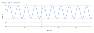
I first generated a 100 Hz, 1V peak-to-peak signal with a 1V DC bias with ADALM and used one of the analog pins on the Arduino to sense the signal at 2000 Hz. I then used Python to collect the voltage data and write it into a CSV file. There appear to be ways to write the data to a MySQL database, too. As the waveform below shows, the frequency is more or less correct, but the peak-to-peak voltage is about 1.5V, 0.5V higher than the actual value, and the signal bias appears to be 1.5V, not 1V.
Therefore, this method of sensing voltage is probably acceptable for measuring the polarity of the voltage in the Ampere’s law experiment. However, some calibration is needed to accurately measure the time-varying induced electromotive force in the Faraday’s law experiment, and the actual voltage in the Ampere’s law experiment.
Looking ahead
My progress is a little behind, as the original design for the Faraday’s law experiment needs to be modified, and the Arduino voltage sensor is not as accurate as expected. To catch up, I plan to spend more time next week to tackle these problems as my schedule appears to be more flexible. I will work on improving the accuracy of the Arduino analog pins and the design for the Faraday’s law experiment.