The beginning of this week was primarily spent preparing for the design presentation, as we needed to finalize our slides as a group and I personally needed to practice for the presentation itself.
However, I also began testing my various piezoelectric sensors this week so I could narrow down and hopefully select a final component that will go into the final design. Initially, I had three piezoelectric options.
- The Flexiforce Piezoelectric Sensor we purchased from SparkFun (Bottom)
- Two FSR 400 Series sensors from Interlink Electronics (referred to as IE going forward) that I had left over from a previous project (Middle)
- Some cheap handmade Piezoelectric sensors I purchased off Amazon (Top)
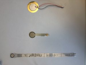
After just some quick initial force tests, it was clear that the FlexiForce sensor was the least easy sensor to use. When tapping the sensor with a level of force similar to that of a hit with a drum stick, the resistance hardly changed, and even when applying as much force as I could with my fingers, the change was still only half that of the other two sensors. On the other hand, both the IE FSR and discount Amazon sensors worked much better, with quick and large responses to only light applications of force. However, the Amazon sensors performed poorly in the test I performed before turning on the camera, which gives me the concern they may act inconsistently if used in the final product. As such, I’ve decided to focus all my testing on the IE FSR going forward, as that one seems to be the most promising sensor.
First clip: FlexiForce
Second Clip: Amazon sensors
Third Clip: IE FSR
After selecting my final sensor, I began familiarizing myself with Fusion 360, so that I can 3D print an initial draft of the drum pad housing. Once I have this complete, I’ll be able to combine it with the IE FSR and the Neoprene rubber sheets to create a prototype drum pad, which should greatly aid in future testing by better replicating the expected endcase environment. Here is the module I’ve developed so far using Fusion 360.
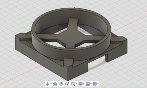
The sensor will be fixed to the raised central platform and all the needed supporting circuitry will be located in the cavity underneath it. Additionally, the gap in the base on one side of the module will be used for connecting this module to another module that will house the ESP32 development board. Lastly, we should be able to attach a 3D printed sheet to the bottom of this module after placing the circuitry inside, which should protect the sensitive circuitry inside.
After designing this module, I began working with the ESP32 development board, as this one is slightly different than the ones I’ve used in the past and as such I expected that I’d have some issues getting it to work as my last board did. As I expected, I have been encountering some difficulties but I expect to be able to run simple code by the end of this weekend.
My plans going forward for the rest of the week are to work more with the ESP32 so that going into spring break I’ll be ready to jump right into coding the ESP32’s ADC features. Once I have the ADC features implemented and I have connected it with my sensors I’ll then begin working on sending the ADC information over USB in a form recognizable by George’s program, which should set me up well for reaching MVP by our goal date next month.