5/8 Status report

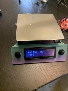
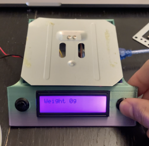
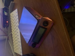
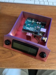
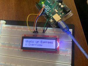
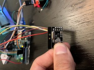
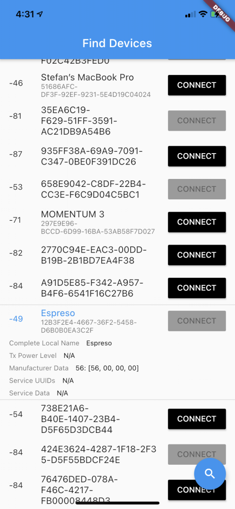
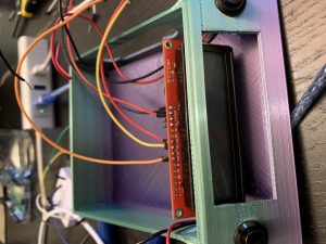
This week I put together the final assembly of the scale and tried to tie in the nRF24 to the application in order to get the weight readings. I was able to implement a timer with the scale and a reset function which is shown in the pictures below. In addition I did a lot of filming and recording of the final video in order to present on the final presentation day


Status Report 4/24

This last week I worked on preparing for the interim demo and completing the ethics assignment. I took the load cell and amplifier that Harper shipped to Pittsburgh and incorporated it into the final scale as you can see below. In addition, I prepared to change the CAD to better house an Arduino since that is the direction of the project. Below are some images of the demo scale

.

Status report 4/10

With the new load cell design I moved into modifying and printing the scale. The hardware for the scale arrived so I was able to slot in the buttons and the LCD display onto the printed model. The screws that hold the load cell in place were not long enough to be screwed into the frame, so longer screws need to be ordered to make the load cell + topper work. I’m going to be working towards putting button control functionality with an Arduino while the PCB is being shipped. Once the PCB arrives, the bringup will hopefully go smoothly and the board can be slotted into the shell without any trouble. Pictures are shown below.


Status Report 4/3

This week I ordered the new scale that comes with a load cell that we are thinking of adopting for our project. The top of the load cell has a different geometry than the one we were previously buying, so changes to the CAD were made. In addition, I received the LCD display, and I was able to get the display working by being powered with an Arduino through I2C protocol. I will begin printing the shell for the new design of the scale this week. A picture of the working LCD display is shown below


Status Report 5/1

This week was busy because we had confirmation that we would not be able to get the PCB in time to make everything work together. Therefore, we started transitioning to a fully Arduino style project. Unfortunately this means that a lot of the physical planning and software we wrote for the PCB is going to have to be scrapped and written anew for the Arduino. I was able to connect a separate nRF24 transceiver to the Arduino and broadcast a signal that we are going to use to communicate the weight that the load cell is reading. I have attached a picture of the device down below. Unfortunately nRF24s do not have capability to connect to BTLE devices, so the only information that can be communicated is one 32bit “advertisement packet”. Luckily since we are only transmitting one value this should not be a problem. I also improved on the mounting of the scale and was able to make it accurate! I have attached a video incorporating the entire subsystem as we have it right now. Unfortunately, the LCD display broke right as I was fiddling with the SPI bus and wouldn’t display anything even after a hard reset. I have attached a photo of the broken display below. It will be challenging to make everything work compactly by the demo, but hopefully we will find some luck along the way. 

Status report 3/27

This week I mainly focused on getting all the necessary information into the design review. In addition, I was able to select the necessary buttons for the shell and prepared the 3D model to be printed. This next week I will work with Harper to start getting the baseline firmware for the scale. There is a STM32 MX programmer that takes is such information such as pinout and schematic and will generate a main.c that automatically configures the necessary peripherals. This is extremely important and helpful as manually setting clock and peripheral registers can take valuable time that would better be used in another fashion.

Status 3/13

This week the team did the design presentation. I was able to put the PCB Cad into the shell design as well as go through the integration of the components into the shell. I still have to add in the correct buttons to the face of the scale. This week we have to work on finish up the physical design report as well as going through the feedback from the presentation. I am going to start working on the base firmware for the scale which will take some time, but hopefully will not be a bottleneck.

Stefan’s Status Report for 3/6

This week I created a a shell for the scale. In addition, I added the PCB model to the design and was able to flesh out a rough housing for the scale. We discussed different materials that we would be able to use. I also used the measurements of the LCD display to create the holes in the shell that would fit. We started working on the firmware for the PCB and will continue working throughout the next week.

Stefan’s Status Report 2/27

Worked on researching different LED and LCD screens to go onto the scale. Had to move the MCU voltage up to 3.3V in order to get and sort of display to work without another LDO. In addition we added pinouts and buttons for the power and physical control of the PCB. I finished putting these changes onto the PCB.

Stefan’s Status Report for 2/20

For the first week of the project, I looked into refining the requirements of our project. We looked at making the BOM for the PCB so that we can place an order ASAP. Next in line is finding a good LCD display + driver to finish off the list of components. We decided on a framework (Flutter), and I did some research on the best way to make cross platform apps. I am going to start working with the team to design the layout of the PCB and the housing, so that we can hit the ground running when it arrives.