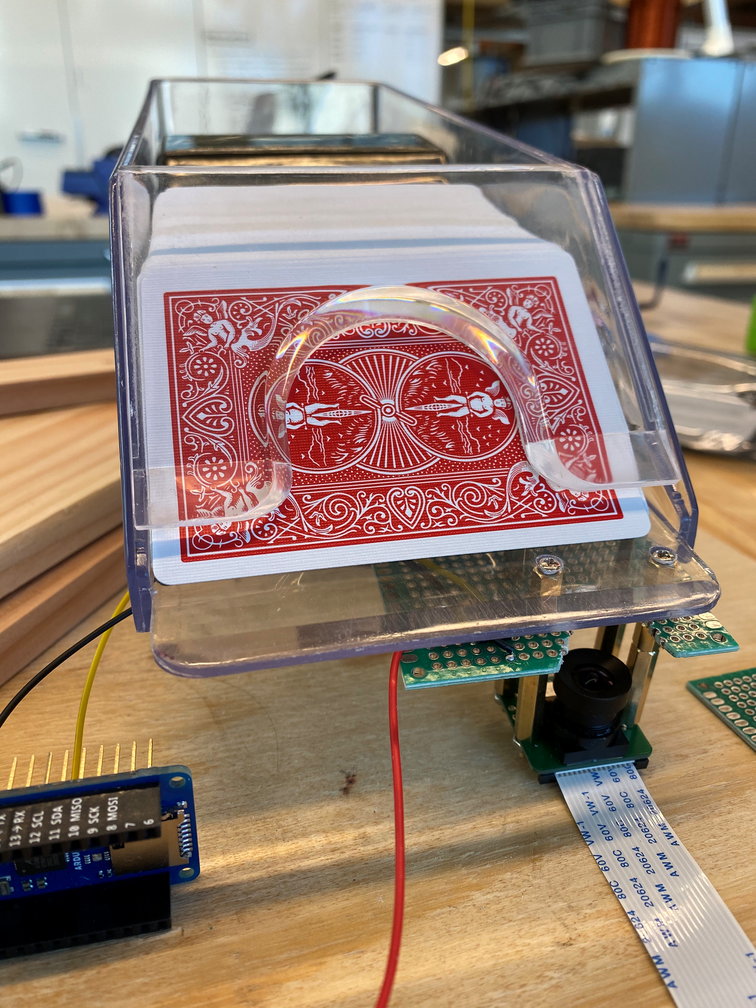
We’ve continued our work on the triggering system this week. After testing several different triggering methods, we found that the QRD1114 reflectivity sensor module was the most accurate and unobtrusive. We created a prototype circuit board using some protoboard. We then experimented with different heights of sensor placement, drilling holes in one of the card shoes and mounting the prototype board and the camera using standoffs.

Using an Arduino, we were able to get very precise readings of when the card crossed the sensor. We then moved on to finding better ways to mount the camera. With our current setup, the image is partially obscured by the standoffs and the PCB. We decided to mount the camera/PCB stack using only the back standoffs and widened the cutout in the PCB.
We then moved on to optimizing for height. Since we want the shoe to be as usable as possible, reducing height was necessary to ensure the cards slid onto the table properly. We wanted to make sure we maintained the sensor height so we began removing standoffs between the PCB and the camera. We found that ~1cm of standoff height could be removed without impacting image quality for classification.
We also began working on the software for the trigger. However, we found that the Jetson Nano doesn’t have an onboard ADC. Since our sensor is analog, we are looking into getting an external ADC. We found a couple modules that may work, but ultimately we plan on integrating the ADC into our PCB design.
We’re currently on schedule for all the hardware components except shipping out the PCB. After looking at various board houses, we found that we could have a design ordered and received with a 5-day turnaround time. This is significantly less than the initial 2-week process we initially planned for. I am confident that the additional testing and prototyping we did in the last two weeks will allow us to only need 1 revision of the PCB. Given our 2 weeks of additional slack time in case a revision is necessary, I believe that we will finish on schedule

