This week I fixed all the bugs (that I could find) which appeared during our team’s demo on Monday. The main two issues we were facing from surface-level inspection were seemingly large amounts of outlier points remaining in the final point cloud, and overall geometric distortion of the point cloud. For example, the iteration of our code that was ready for the Monday demo seemed to have two top layers to the scan of the cube, even though it should be one flat surface.
After further inspection of our code to generate the point cloud and significant research into similar applications such as path tracing to perform realistic lighting simulations (both path tracing and laser triangulation require ray-scene intersection algorithms, in which the slightest incorrect implementation can cause unrecognizable visual outputs), I realized some of the problems were a result of me making small errors that propagated to have a hugely unreliable output.
To explain the cause of the bugs, I will first re-introduce the problem in a fresh light to see where we went wrong in our first attempt. To reiterate, the core of the laser triangulation algorithm is finding the “depth” of each pixel along the laser line in an image. Once we have this depth, we can compute the 3D coordinate of the laser point by travelling towards that pixel’s direction into the scene by the depth. This depth can be computed by shooting a ray from the origin of the camera through an imaginary sensor where the pixel should be according to the perspective/pinhole camera model, until that ray intersects with the plane of the laser line, which is unchanging since the laser line is not moving. The image below illustrates the various components of this process. Note that in a real-life scenario, the lens of the camera and its curvature introduce some polynomial distortion to the image we would have to deal with. However, since we are simulating scans, we are using 3D software (Blender) that provides easy to use ideal perspective/pinhole model cameras, so this distortion is not necessary to model.
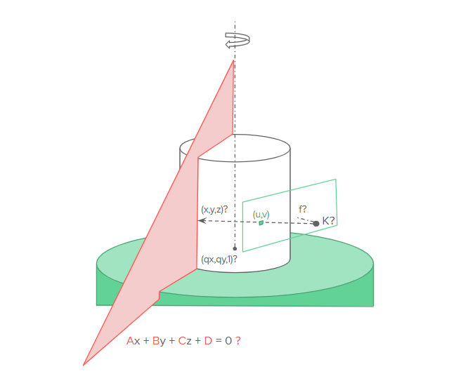
The point labelled with K is the origin of the camera, and (u,v) is a pixel in the screen that is red from the laser. (x,y,z) is the 3D position in world space where the pixel effectively maps to on the object, which is also the ray intersection with the laser plane. Assume in this diagram all values are known except for (x,y,z). Also it is important to note that (x,y,z) is a coordinate in world space where the intersection occurs, but it is not the effective coordinate in the object space where our point cloud resides. To get the corresponding object space coordinate, we need to reverse rotate the coordinate about the center axis by the rotation amount for the image we are processing.
With that refresher out of the way, below I will go over the process I went through this week to resolve the noticeable issues with our demo:
- An important part of writing software is anticipating bugs and exposing as much information as possible during development to make catching those bugs easier down the line. Since this capstone is not a massive software project, we did not initially develop the codebase with logging and other explicit debugging mechanisms. As soon as issues were detected in the demo prototype, I wrote up a way to visualize various aspects of the code which could aid debugging. This visual aid includes the global x,y,z axes, the laser plane, the laser normal, and the camera origin, which is overlaid on the generated point cloud so that issues among the relationships between these objects can be easily detected. Below are two images showing a point cloud along with the debugging visualizations.
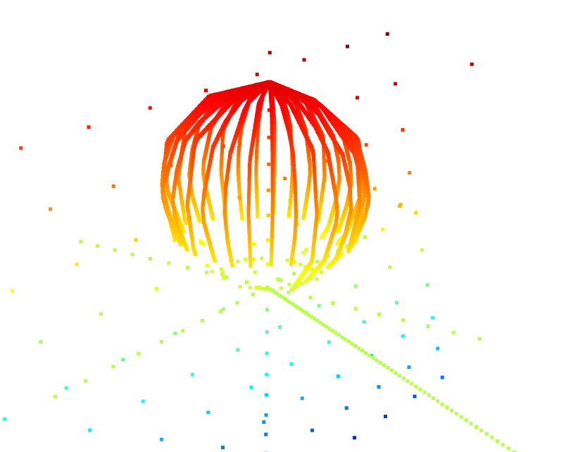
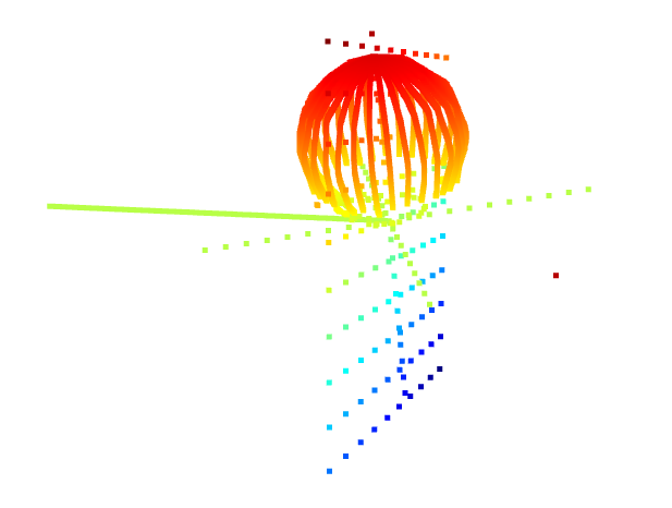
- The first issue I immediately noticed after having these debugging visualizations is that the ray-plane intersection points were not exactly on the plane but were at a slight offset instead. The reason for this is that I naively modeled a plane as just a normal, without considering that the laser plane does not necessarily travel through the origin, and thus must be modeled as a normal along with the distance from the origin. Fixing this issue, the point clouds became much more reasonable, and most of the outliers were removed. However, geometric distortion was still prevalent across the scans.
- The next issue was that I was shooting the rays through the bottom corners of the pixels instead of through the middle of the pixels. This is not ideal behavior and I added an offset to the sensor point the ray should travel through so that it travels through the center of pixels instead of the corners. This made the results slightly better.
- At this point, geometric distortion was still there. I eventually realized that the matrices I was copying from the blender file which determine constants regarding the camera position and direction, and the laser plane, were only being copied at around a 5 decimal point precision. I figured out how to extract the true values of these parameters and at this point the code seems to be working as originally intended.
- The then working version was slower than we anticipated. I added code to time each component of the script to see what could be optimized, and gradually increased the performance of the script until it met our 5 minute scanning requirement (for 1000 images, the computation currently takes about 30 seconds to generate the point cloud).
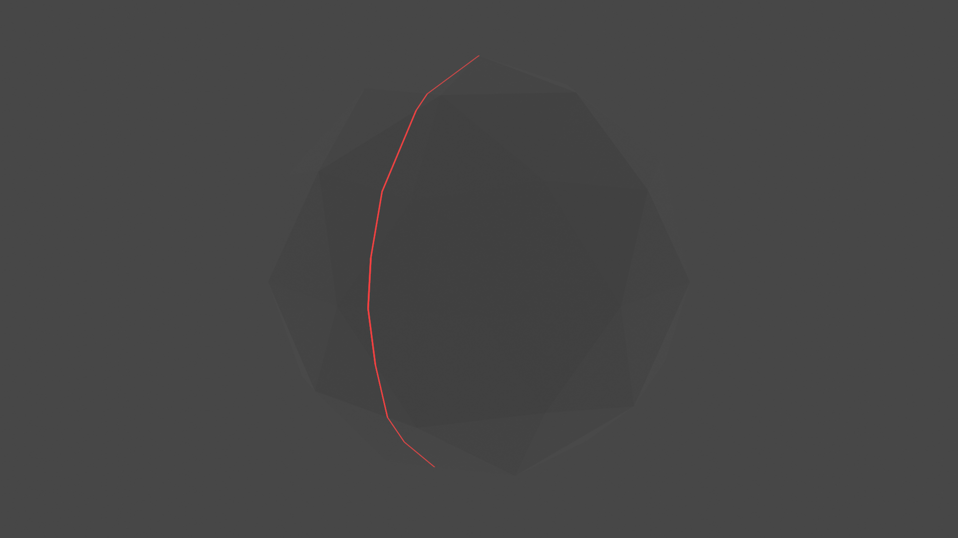
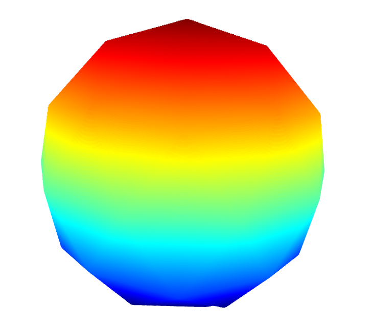
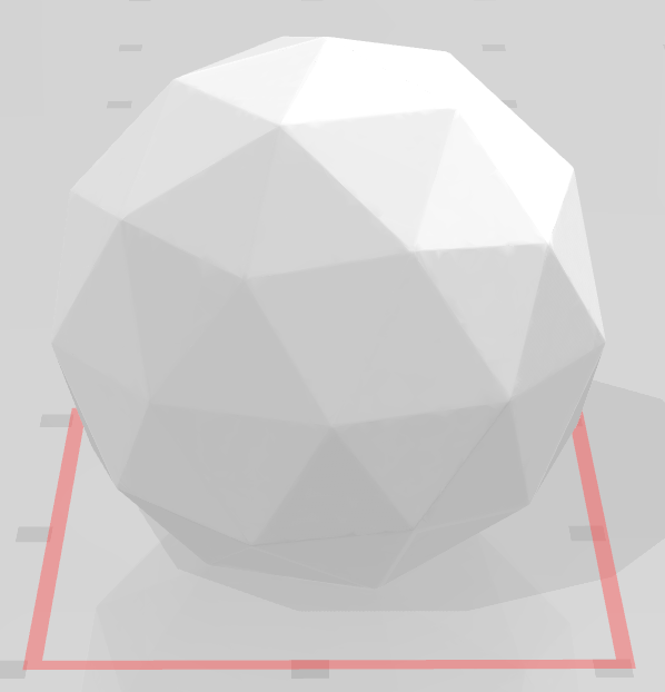
The current version seems to work very well for the icosphere object. The below images are of the generated point cloud from the scan, as well as the triangulated mesh, with 1000 images captured during the scan:
I am now back on schedule with all the bugs fixed from the demo. The next step is to implement the verification engine to ensure we are meeting our accuracy requirements for each benchmark. Tian is working on a more adaptable method to perform triangulation for objects with holes/occlusions, and Jeremy is working on introducing noise and other factors in our scan. I believe our project has low risk at this point, since we have a working version completed.