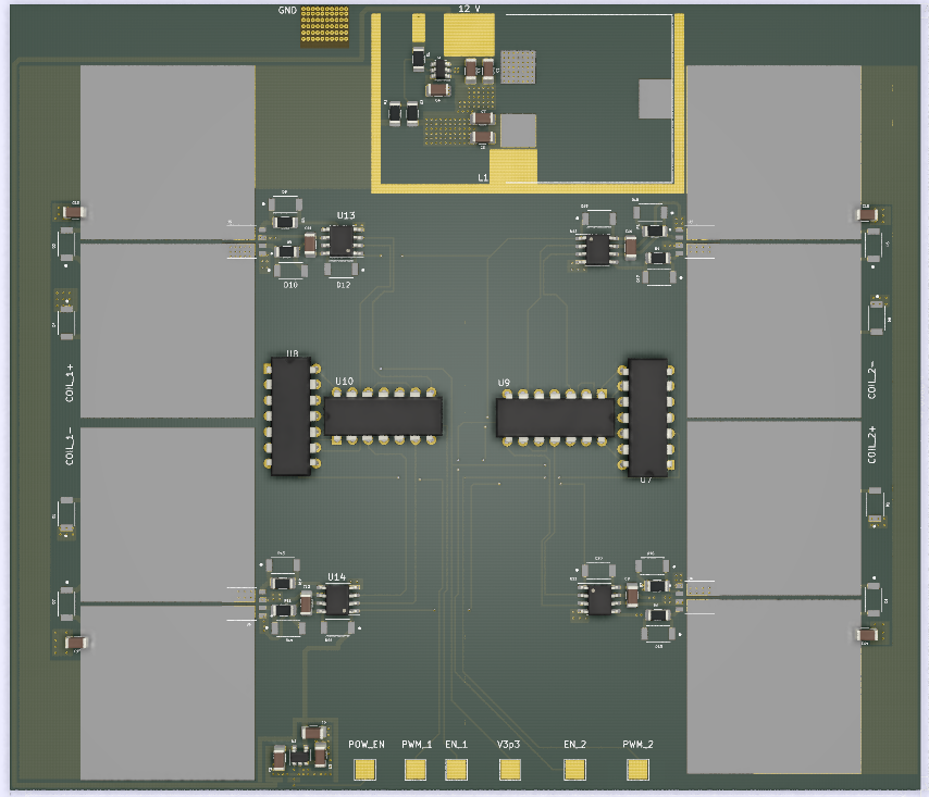
This week, I placed the finishing touches on the high power motor controller board. This mostly consisted of adding charge reservoir capacitors to decouple the H-bridges locally so that the voltage at the H-bridges won’t droop during operation. I also tidied up the PCB silkscreen so that the component designators are easily visible:
On JLPCB, the design should cost roughly $28.50, with an additional $17.55 for DHL shipping for 5 units. Thus far, shipping to the US with the aforementioned courier has not been impacted. With an estimated build time of 3 days, a shipping time of 4 business days, and a delay of 3 days (due to Coronavirus), we can get our designs done with a lead time of 10 days, which is still reasonable.
Due to changes in the scope of our project due to Coronavirus precautions, I’ve begun investigating the possibility of using a smaller 4096 step stepper motor (MIKROE-1530) for driving our project’s barn door compensator. This motor takes 5V (which would require a redesign of the primary SMPS), but only consumes 0.1 A per phase. Using IRLR6225TRPBF MOSFETs means that the static power consumption is less than a milliwatt, allowing the omission of area-intensive drain pads that would ordinarily be used for heat dissipation. The electrical complexity of the gate drivers also drops due to the motor being unipolar, allowing the usage of simple buffers (LM5114BMFX/S7003094) instead of proper half-bridge gate drivers like the LM5109B. Overall, changing over to this motor will allow the resultant motor controller board to be much smaller, giving us more headroom in the budget since the US-based PCB manufacturer we were planning to use as a backup in the case of further Coronavirus-based shipping restrictions charges by the square inch. Assuming that we fix a rotation rate of 1 RPM for this motor for the barn door compensator, the motor controller board will need to support 68 steps per second (which is well within the capabilities of an Arduino’s ADC to detect and record for debugging purposes).
Next week, I intend to consult with the faculty on the feasibility of performing the PCB fabrication through JLPCB in light of potential shipping restrictions. If it is possible, then I will perform a design review of the motor controller with Dr. Mukherjee and have the board ordered to Kenny’s location for assembly. As a contingency, I will proceed with the design and layout of a motor controller for the new 4096 step motor with the goal of keeping total PCB area below 4 square inches ($20 dollars on OSHpark).