This week, I first worked on finalizing the Bill of Materials. I specc’d out the exact parts for the Text Display, Face Display, Motors, and the Motor Driver. The Text Display will be a 5in x 3in LCD screen, which connects to the Raspi through HDMI and takes 5V and 250mA power. The Face Display will be two 2.3in x 1.5in TFT screens for the eyes, that communicate to the Raspi via SPI. They need 3.3V and very little current.
Next, I did research into determining which motors we would need for the robot arms. I determined that the worst case scenario for the torque for a 6in x 2in x 2in arm made with acrylic would have a mass of 464.08g (24in^3 * 1.18g/cm^3). With the center of mass in the middle (3in = 7.62cm), the torque would be 3.53kg/cm (0.464kg * 7.62cm). This means that we could use an inexpensive servo motor. I found 3001HB servos in the Robotics Club, which have a torque of 4.4 kg/cm at 4.8V which is sufficient for this project. One major issue, however, is that these servos can draw up to 1 amp of current. After looking into ways to manage that, I decided that the method of putting a 470uF capacitor across the power rails for the servo would help mitigate large spikes of current draw.
After determining that we would use servo motors, I found a PWM motor shield that could connect to the Raspi and connect up to 16 servos. It communicates to the Raspi via I2C and comes with reverse polarity protection and circuitry to put a capacitor on the power rail as I had discussed before.
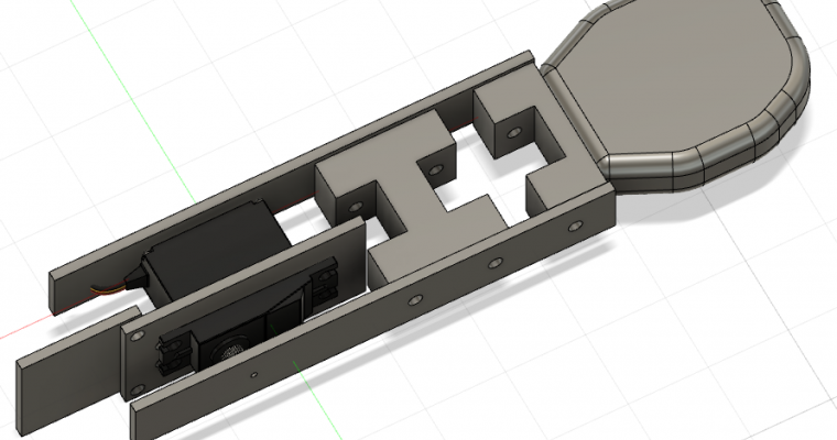
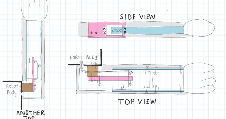
Finally, I started designing and CADing the robot arms. I am quite rusty with CAD, and have never really used Solidworks, so most of the time I spent this week was acquainting myself with the software.
Next week, I would like to set up the Raspis and work on the software to display eyes/text. I would like to have the design and most of the CAD for the robot arm done by the end of next week as well.