Status Update – Matt (03/23/2019)

This week I spent a lot of time refining the circuit simulator. I also worked on developing some tools by which the simulator can be easily tested against a variety of input waveforms. At this point, I am very confident that components such as resistors, capacitors, and inductors work correctly. This is more than enough to build basic filters. In order to implement some of the guitar pedal effects we want, we’ll also need to test diodes and transistors. This could prove to be a bit more challenging, as the IV curve for a transistor is not really the same from device to device like it is with capacitors, inductors, and resistors. Ultimately, implementing these components will probably require us to read some datasheets for the exact transistors/diodes that make up the pedal we are trying to simulate.

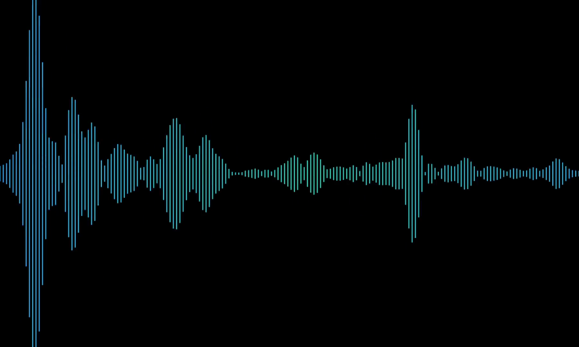
I also worked on a test suite of small circuits and waveforms that can be used for testing. I wrote a small script that generate waveforms (either sinusoids, square waves, or high frequency noise) and export them in the format that the simulator expects as input. I also manually created a few new circuit netlists for testing. Now that we have our test suite set up, we are able to look at some more complicated waveforms. For example, here is high frequency noise being passed through an RLC low pass filter. It is clear that the filter smoothes out some of the high frequency components of the original signal.

This also allows us to test the models for individual components using extremely simple circuits. For example, we can verify that our capacitor model behaves in a reasonable manner by looking at the following waveform, showing the response of an RC filter to a square wave:

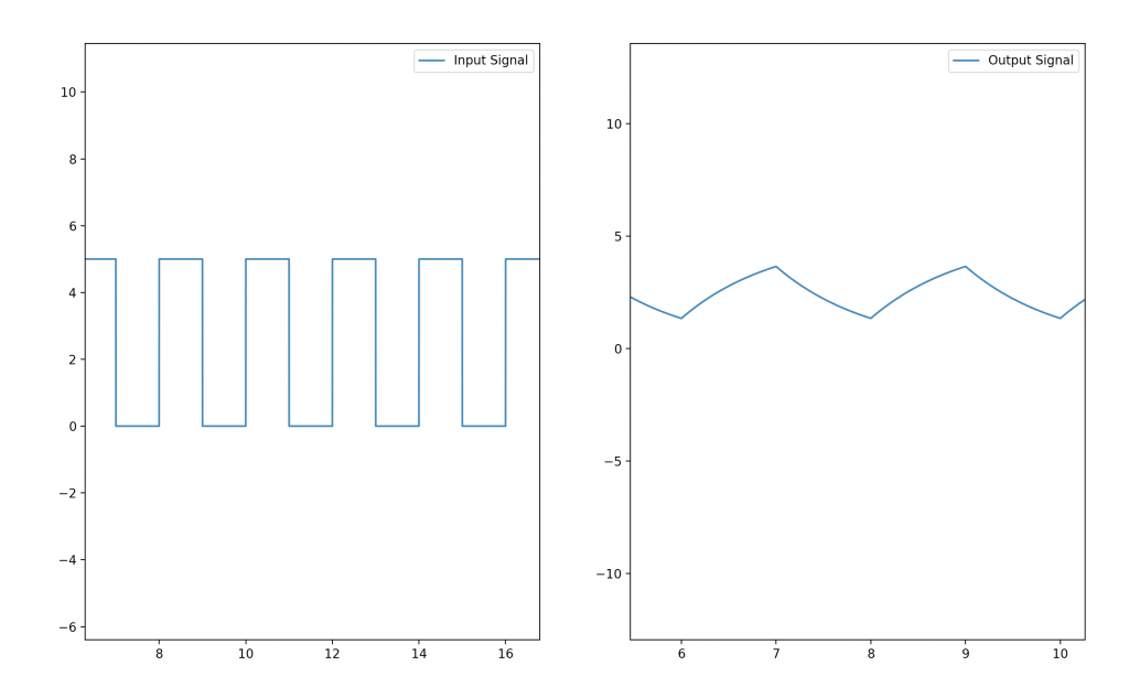
This allows us to do a basic sanity check of our component models–it is clear from this waveform that the capacitor charges and discharges as expected.

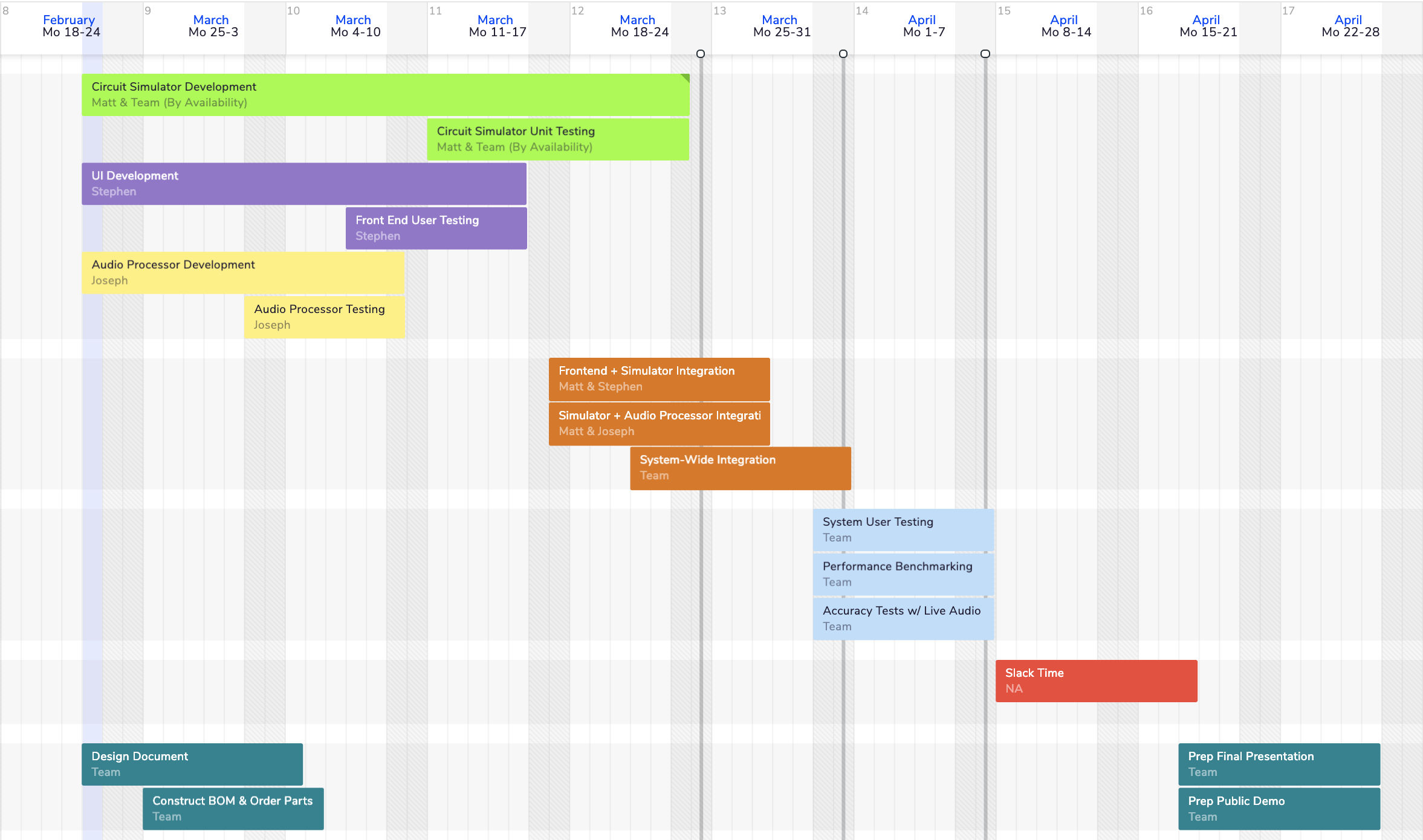
This allows us to have higher confidence in the accuracy of our simulations, but ultimately it is still a qualitative approach to testing. Much of our efforts over the next week will be spent on implementing our full test bench to enable us to really quantify our error/accuracy. We also plan to meet on Sunday (3/24) to integrate all three of our components ahead of the in-lab demo which is right around the corner. This will probably take a fair amount of my available time next week, and we also lose one working day in lab for the ethics discussion, but I hope to also have some time to test the diode model in the coming week. I ultimately think that I am fairly on-track, though I do think I should speed up my development pace a bit in order to account for the fact that bugs are likely to arise as we progress, and I want to have time to deal with them without killing our schedule.

Status Update – Team (03/09/2019)

This week, we spent some of our time together working out the final details of our design ahead of the design document that was due on Monday. One of the big things this involved was hashing out our test procedure in greater detail than we had ever done before. Ultimately, we decided on a protocol (which we discussed in lab this week) that involved using an audio splitter to derive our reference and test signal from the same source at the same time. We could then feed one of these signals through a real guitar pedal, and another through our simulated version, before using normalized cross correlation as a metric to measure the similarity between the two.

We also placed an order for parts just before break. Professor Sullivan is kindly allowing us to use his audio lab, which eliminates the need for many of the components we had planned to order. However, we did request a few parts such as a reference guitar pedal, and the splitter cable we need. We chose a DIY pedal that had simple circuitry on the inside, and we carefully chose one that consisted entirely of components we plan to support in our own simulator.

Much of the other work we have been doing lately has been on our own individual parts. Matt has been working on the circuit simulator, Stephen on the UI, and Joseph on the audio processing. We ultimately hope to spend about another week or two on development and unit testing before we begin integration. Some parts of the project have made good strides this week, but there’s still a lot left to do, which is why we all intend to dedicate some time over spring break to getting our components up and running.

Status Update – Matt (03/09/2019)

The first action item for this week was to work on the design document, which we submitted Monday afternoon. This was really a team effort–the three of us got together for several hours on Sunday to work on the document as well as go over the feedback from our design presentation. I think that this was a very helpful step, which allowed us to get on the same page about the vision we had for the project and what steps we were going to take to get there.

One thing in particular that we had to dive deeply into was our testing procedure, as there were still several unanswered questions on that front, which were pointed out in the design review. The main question we face is how to determine if our pedal simulator is truly accurate. After some careful thought, we devised a testing plan based on a metric called normalized cross correlation, which can be used to measure the similarity between two signals. Our original hope was that we could simply use a physical guitar pedal as a reference model, and compute the normalized cross correlation between the signal coming out of that pedal and our simulated pedal. This left unanswered several questions, such as how do we ensure that the input signal is consistent for the simulated pedal and the reference pedal? How do we account for phase differences that can occur due to measurement timing? We ultimately revised our naive testing procedure to use an audio splitter to derive the reference and test signal from the same source. To account for phase differences, we will take the normalized cross correlation between our reference and test signals at a variety of phase offsets, treating the maximum correlation as the “score” in our testing procedure. I think that it was particularly valuable to work out how the testing will work for me, since I am primarily working on the pedal circuit simulator.

This brings me to the other work I got done this week. At this point, the simulator seems to be able to handle all types of resistor configurations, as well as some nonlinear components such as inductors and capacitors. I think that some further unit testing will be required before I am ready to declare this phase of the project a success, and I will be working on this near the end of spring break. However, I am very satisfied with my progress this week as it relates to the capabilities of the circuit simulator.

As far as next steps and my schedule moving forward, testing is going to be a really big deal in the next week or so. I’m hoping to build up a suite of circuits that have well known behavior, such as RLC filters, so I can perform basic sanity checks to tell whether my simulator is producing sensible results. I also hope to add models for other nonlinear components such as diodes and MOSFET transistors, which we hope to be able to support in our final product. However, testing the existing infrastructure is going to be my priority, rather than adding support for new component types, until I am satisfied with the simulation accuracy for the components already implemented.

Since circuit simulation is uncharted territory for me, I’ve been working in Python for now so that I can get comfortable with the algorithms and techniques in a language that allows me to iterate rapidly, make changes on the fly, and reason about the code without worrying about low level details. However, I also know that eventually this simulator needs to be fast. At some point in the next two weeks, I would like to start porting over some of my successful experiments to C++, which should result in better and more predictable performance.

Overall, I’d say I’m pretty on schedule based on what we submitted as out team schedule in the design document. I also have a lot of free time over spring break once I get back to Pittsburgh on Thursday, so I should have an opportunity to keep pushing forward this week.

Status Update – Team (03/02/2019)

This week, we spent the majority of our group meeting time working on the design review, particularly rehearsing for the presentation. We’ve also spent some time looking over the feedback from our design review, and discussing how this could impact what we submit for the design proposal document this Monday. In particular, we’ve identified from our feedback the need to lock down a more concrete, well-researched testing plan. This is something that we plan to research on Sunday during our group meeting and incorporate into our design document.

Besides these small group items, the majority of the work we’ve been doing has been on our own independent parts. Matt is currently working on the circuit simulator, Stephen is working on the frontend, and Joseph is working on the audio processor. This week, we unfortunately had to commit an unusually large amount of our time to the design review as well as midterm exams for other classes. This is something we think will be an abnormal occurrence, and we should be able to get back to normal this week, as we make a final push to get a lot done before spring break. We recognize that we are a bit behind our planned schedule, which is why we hope to be able to get back on track this week by putting more hours into our project than normal across the board. The fact that we don’t have any deliverables due for some time after our design document will also surely help.

Updated schedule:

The schedule contained in our design review slides was constructed relatively recently, and should still be up-to-date. Within some of the larger goals listed on our schedule, we are hoping to accomplish some of the following tasks in the near future (this week):

  • Minimum working UI
  • Audio processor capable of handling audio signals of the format provided by circuit simulator directing output speakers
  • Circuit simulator works for simple circuits (<7-8 components, voltage source connected directly to ground)

Status Update – Matt (03/02/2019)

This week was primarily dedicated to our design review. As the presenter for our team, I spent a large chunk of my time rehearsing and refining our material before Wednesday’s public presentation. In the presentation, I covered the basic design for our system, testing plans, and our schedule for the rest of the semester. The slides for our presentation can be found in this post.

Aside from the design review, I have spent a couple hours working on the circuit simulator as well. I have still been having trouble getting an accurate simulation to work with nonlinear components, so quite a bit of my time has been spent researching the best ways to do this. In particular, I have been reading through the documentation and source code for SPICE (this website offers some nice guides) in order to see what I could emulate feasibly in my own simulator. I have also produced a small amount more code (on the basic-component-simulator) branch in my repository, which was shared in last week’s post. However, I still do not have a working demo to show involving nonlinear components, which I really was hoping to have by now.

I’m starting to worry that I may be falling a  bit behind schedule, which is why I hope to dedicate ~20 hours to the circuit simulator this week. This, combined with the fact that there are no other major capstone deliverables this week, should hopefully enable me to finally break through this barrier. I think this would leave me in a comfortable place heading into spring break. This past week, I’ve had to deal with several midterm exams (both as a student and a TA), which have occupied 30+ hours of my time, between studying, writing questions, proctoring, and grading. I actually have no more exams to deal with until finals, so this should be another factor that enables me to get more done going forward. I also plan to stay in Pittsburgh for the majority of spring break, which should give me some extra time to get ahead.

By next week, I’m hoping to be able to test out basic filters and pedals. I don’t expect that they will be perfectly accurate, but I should at least be able to get a waveform in and see a waveform out on the other side. If I can’t get this delivered by next week despite good effort, I think it will be time to reconsider our approach to circuit simulation and perhaps consider some alternatives just in case things don’t work out as intended. For now I’m going to spend one more week focusing on getting things to work before jumping to any extremes.

Status Update – Team (02/23/2019)

Risks

The most significant risk is still that the circuit simulator will not be fast enough to process live audio. We haven’t come far enough in our implementation yet to confront this problem directly, but we strongly believe that this could be an issue that we will face in a couple weeks. Our approach to this problem has not changed since last week. We plan to run each user-specified circuit through a preprocessing phase, where it will be simulated at a variety of operating points, in order to speed up live simulation. We also plan to allow pedal designs to be tested against recorded audio, which loosens the time constraints brought on by live simulation.

Design Changes

There was a change in the structure of our program. The audio processing module is now only responsible for loading audio inputs and writing outputs, and is not responsible for modifying the audio signal. This change was necessary as we determined that it’s not feasible to derive transfer functions for circuits whose output is dependent on the current state. Thus, the circuit simulation engine is now responsible for the audio modification. The only real loss from this change was the time we spent researching and prototyping. Moving forward, I think we have a much better understanding of how circuit simulators work and what our project will look like, which will prevent us from making big changes in the future.
We also spent a lot of time ironing out little details in our design which were not finalized last week. A good example of this is the exact signal passing protocol between the audio processor and circuit simulator. We believe that these kinds of refinements are naturally tied to next week’s design review presentation, which requires us to have thought out the small details in our design and implementation plan.

Schedule

As we’ve become more familiar with the technical challenges we face, we have naturally been able to get better estimates for how long various things will take. Here is our new projected schedule:

Status Update – Matt (02/23/2019)

This week, I’ve been splitting my time between working on the design review and working on a basic circuit simulator. At first, I kind of felt as though the design review was somewhat distracting me from getting to work on the actual implementation of the project, but over the course of this week, I have come to the conclusion that the design review was actually really useful because it forced me to consider aspects of my design that I had previously glossed over and formulate ideas in writing that had previously only existed as fuzzy thoughts in the back of my mind.

Design Review

With that in mind, the first thing I did this week was lock down a formal design for the circuit simulator. This design is shown in the block diagram below.

Ultimately, the circuit simulator is going to be broken down into two main parts. The first is a circuit parser, which translates a netlist description of a user’s circuit that was passed to the simulator from the front end into a custom, internal representation. This representation is really just a vector of components and some metadata to keep track of which nodes everything is connected to. From there, this internal circuit representation can be passed along to the simulation engine, which is responsible for doing most of the heavy-lifting. The algorithm we settled on involves several steps:

  • Construct linear approximations for all non-linear components
  • Perform KCL and Nodal Analysis to derive system of linear equations
  • Initialize solution matrix to initial “guess” state
  • Use Gauss Jordan Elimination to solve system of linear equations
  • Continue to iterate using Newton’s method until solution has converged to within acceptable error rate.

We also plan to pre-simulate complex circuits against a variety of states and sample inputs, with the hope that this can enable us to do faster processing of live signals at the cost of some additional up-front processing time.

Simulator Implementation

In the leftover time after preparing for the design review, I’ve also had a chance to work a bit on the implementation of the actual simulator.  In my last status update, I mentioned that it was my goal to be able to simulate a basic RC low-pass filter this week. Unfortunately, I thing that goal was overly optimistic for two reasons. First was that I underestimated the time that I would have to spend preparing for the design review presentation, which obviously cuts into my implementation time. Second, simulating an RC filter, though it is a seemingly simple circuit, is fairly complicated as far as the simulator software is concerned. This is because capacitors are nonlinear components, which depend on energy stored on past iterations of the simulator. This makes the simulation much more complex, and I’ve run into some bugs in the implementation that I have not yet had the time to resolve. I’ve also decided that I am going to write a proof-of-concept version of the simulator in Python first, then port it over to C++ once the kinks are worked out in the simulation algorithm. This is because Python allows me to debug, iterate, and try new things much faster. Since we’re not yet worried about speed, I felt as though this could be a good approach to take for a week or two until I’m comfortable with the algorithms behind the simulator.

However, I was able to complete some things this week. For example, the netlist parser is nearly entirely completed, and it supports components such as resistors, capacitors, diodes, and voltage sources. Probably the only remaining component that we would need to add would be transistors, which are a bit unique because they are not two-ported components. An example of the netlist representation of a basic RC filter is shown below.

RESISTOR r1 0 1 100k                    # 100 kohm resistor
CAPACITOR c1 1 2 100u                   # 100 microfarad cap.
VOLTAGE_IN vin 0 2 voltage_in.txt       # voltage input
VOLTAGE_OUT vout 1 2 voltage_out.txt    # voltage output
GROUND 2

The code used to parse files like this can be found in this Github repository. This repository does not yet contain the code for the simulation engine.

Outlook

I would say that I definitely came up short of the goals I set for myself last week. However, I think that I can still be on track given that my goals last week were a bit ambitious. In fact, once the simulator is capable of handling an RC filter, adding diodes and inductors is really just an extension of the same principles. The next major hurdle from there will probably be adding transistors, then making sure this code runs fast enough to meet our goals. Next week, I truly do hope to have an RC filter running against recorded audio, and perhaps a bit of work done on inductors and diodes as well.

Project Proposal

This post contains our project proposal, a presentation which Joseph Kim delivered during a class meeting on Monday, February 4. The presentation covered the rough scope of our project, including the problem we intended to solve, the challenges we expect to face along the way, our division of labor and schedule, and a brief overview of our initial technical approach.

The slide deck for this presentation can be found here.