23 February
Team:
The biggest risks for this week are still contingent on the hardware components of the project. Sam and Lily are steadily making progress with the software with a few hiccups. We’ve made the necessary purchases to ensure the cube state detection is done in a controlled environment. While the solving software is slightly behind, the current redesign is more robust and is easier to comprehend. We’re confident in our abilities to get the motors working, but the biggest concern is with frying or breaking our circuits once we start working with multiple motors in parallel. To mitigate this, we’ve done the research and even asked on forums to ensure our current setup is feasible and safe, and added capacitors for each of the single motor setups.
The biggest change so far is the decision to change our power supply from 12V 2A to 24V 5A. This change will cost us $19.99 and bring our total purchases to $414.97 and considering we’ve already purchased everything necessary for the project we still have plenty of cushion left if things were to go wrong with our current equipments. The addition of the capacitors can be taken from the ECE labs. On the software side, the Beginner’s method implementation requires quite a bit of work but will be completed in parallel to the Arduino-motor interfacing.
We believe that we are still mostly on track given our current team conditions.
JT:
Worked with Sam again on the cube state detection software. After the first iteration, we decided to make some design changes to improve the quality of life for the project. I suggested we minimize the color scanning region so that our readings would be easier to align and more accurate. On top of this we decided to add a live color indicator. This maximizes our accuracy as we can see what the computer is reading before we store the face state. I also ordered a softbox item tent and webcam to use for our cube scanning. OpenCV has proven to be very fickle depending on the lighting conditions. Our cube orders came in and we found all sticker variants and model types had varying results with our software. Using the softbox and webcam will allow us to zero in on the correct HSV ranges for the most accurate readings.
Wednesday the last of our essential parts came in to beginning work with the stepper motors. With the stepper motors, drivers, and Arduinos we can begin working directly with the hardware. I’ve read more forums and tutorials about how to control a single motor and it’s my understanding that we can use a single motor setup 6 times in parallel with our power supply. Concerning the Nema-17 stepper motors, they complete 200 steps in a single revolution. A single step moves 1.8 degrees. The motor drivers take two inputs, n-amount of steps to turn and which direction. With the drivers, the code to control the motors should be more straightforward than we initially thought. Our concern is with controlling all 6 motors at once without frying anything. I decided to change our power supply to 24V with 5A to ensure all motors work at full capacity. Our initial 12V 2A power supply only seemed sufficient for one or two motors. I also bought a simple adaptor to plug in our new power supply to our breadboard.
Lastly, I began to put together the slides necessary for the Design Review slides due this weekend. I created block diagrams for the two main parts of our project. I also made a more in depth circuit diagram for the stepper motor and driver configuration.
With this in mind we’re still on track to make good progress before spring break. It’s possible that after Monday’s mandatory lab we could be further ahead and be able to add more features in the software. By the end of next week I am confident I’ll be able to fully control a single stepper motor with our Arduino. Best case scenario, I’ll be able to control multiple motor arms assuming our larger power supply arrives.
Lily:
This week, I continued to work on the software design for the Beginner’s method cube solver. I was able to develop representations of the cube faces, colors, and moves. However, I came across some trouble in the implementations of the cubie pieces. A Rubik’s cube is physically made up of pieces called cubies (12 edge, 8 corner) and a six-armed spatial cross containing the center pieces. In order to represent the appropriate cubies as edge or corner pieces, certain cubie pieces in my implementation need to be linked in position and color such that when a rotation operation (a move) is executed, the software does not lose track of the cubie positions and linkages.
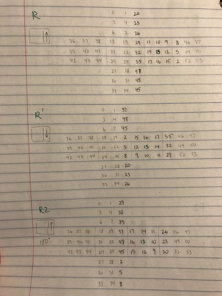 Figure 1: Cube pieces and cubie linkages
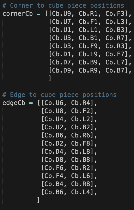 Figure 2: Code snippet of the cubie linkages
With this in mind, I’ve been working on restructuring my cube and move definitions. Based on my newer cube representation with cubies, I have also been working on taking in a string representation of the cube configuration and outputting a text-based mapping for viewing purposes. This string representation of the cube configuration will be an output from the cube state detection on which Sam has been working. If time allows, the text-based mapping can be converted to an actual UI complete with colors and cubie designations.
In addition, I have been developing the cube rotation move definitions/mappings and translation of cubies with respect to the different moves. These were tricky to comprehend from a two-dimensional standpoint so I had to write out the effects of each type of rotation (see Figure 3) before translating into code. After the 18 move definitions, all that is left is to write the actual solving algorithm for the Beginner’s method, which works by solving the cube layer by layer and permuting the top layer until it reaches its solved state.
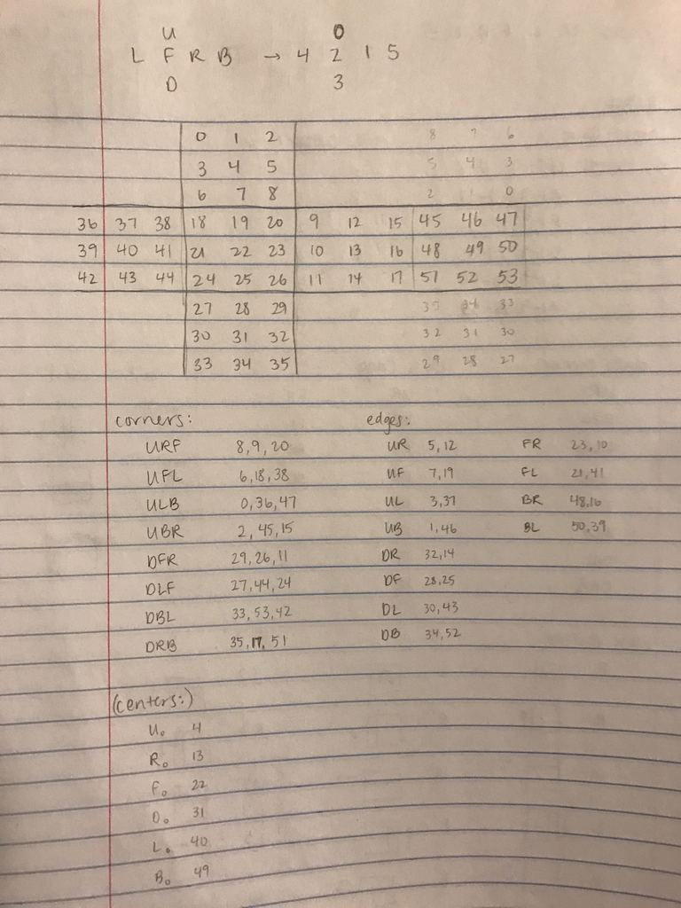
Figure 3: Mappings for three of eighteen rotation moves
Due to all of this, I am a little behind on schedule with the implementation of the Beginner’s method. When making our initial schedule, I knew this part of the entire project would take at least two weeks, especially with the goal of requisite and thorough software design, and I hope to catch up while also work on the Arduino-stepper motor interface these next two weeks before spring break.
Sam:
This past week, I improved upon the cube state detection software. JT and I discussed ways to improve the design experience for the cube state detection. One new and important feature implemented is the live color tracker that is in the top left window of the OpenCV window. This indicates the current color being tracked and is essential for the validation aspect to ensure that the colors being detected are in fact correct. In regard to scanning a side of the cube, the experience is still the same. The user presses the spacebar to capture a side of the cube and the mapping algorithm stores the side of the cube in a data structure. I also iterated on the HSV values for color detection. Lighting is still an issue in the sense that our cube state detection doesn’t work uniformly the same everywhere. Thus, after discussing this with JT, we decided that in order to make our project more robust, we need a softbox to standardize the light in which the cube will be scanned.
I helped order the softbox and the webcam that will be needed for the next part of our project. The cubes, motors, and motor drivers came in. With the cubes that came in, I started experimenting with different color schemes for the cube state detection. We have both stickerless and non-stickerless cubes that I will iterate upon the software next week so that it is compatible with both. I also worked on piping the output of the cube state detection with Lily’s code for the solver so that the interface is seamless. This part of the project is done and we have the desired output for the cube state detection into the solving algorithm. Lily will discuss more about this mapping and interface in our software.
In parallel, I started research on how to communicate the solution string from the solver to the Arduino using serial communication. There are a couple methods we can choose to use. I will iterate on this over the course of the next week so that we have a better design idea of how we will communicate between a mac and an Arduino Rev3. I will also help JT with the motors and motor drivers. The goal is to first be able to control 1 motor and spin one face of the cube. Once the softbox and webcam come in, I will finalize the HSV values to detect color and completely wrap up the cube state detection part of our project. I will also fill out details for our design review slides.
I believe our team is making good progress still and we are on schedule to finish on time. We are hoping to have a very productive week now that our parts are in.
0 Comments