Ethan:
This week, my main focus was preparing for the demo. In order to do that, I had to do a lot of work to finish the v0.1 of the networking stack. For the networking stack, this week I implemented routing link tables as well as converting the existing IPv6 code to use no dynamically allocated buffers. This also involved rewriting several previously buffer heavy implementations of networking functions with zero copy replacements. In some areas of the code, dynamic message sizes forced a worst case stack allocation to avoid a buffer overflow. As as result, while incoming packets are only bounded by the static Wi-Fi buffer, outgoing packets are artificially bound to a maximum MTU of 1200. This will probably change going forward, but more improvements are needed to the network stack first.
The network stack is also unstable, and crashes if it gets too many packets.
In addition, my other main focus was bringing the software to a point where it was able to be demoed. This required first working on the networking stack, and bringing to a point where it can talk with other IPv6 complaint devices in a minimal direct link. Full packet routing is still being implemented, and is not yet ready. For the demo, I worked on researching how linear PCM packets are processed, as well as working on a demo that used the IPv6 stack to forward audio from a target computer to the headset. Our next goal is to implement routing, so that the headsets can relay audio to each other.
We also need to continue to improve our audio playback protocols and buffer systems. Currently the audio playback is choppy, because even small variations in packet delivery time can cause the DAC hardware to miss it’s deadline. This is very noticeable for even small interruptions. In order to address this, we are working to develop a packet buffering and synchronization scheme to make the headphones more tolerant to jitter in packet arrival times.
I ended this week by completing the first audio demo, and testing it tonight. As mentioned earlier, it does not sound very good, and more refinement is needed for demo day.
Michaela:
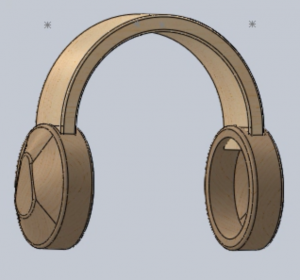
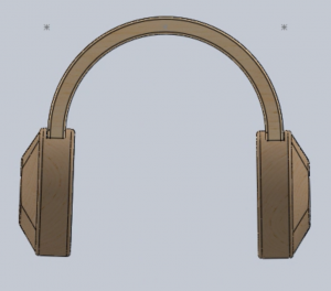
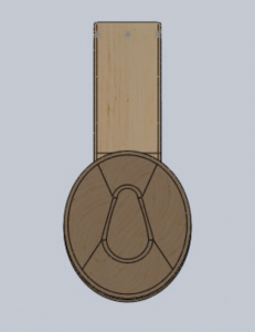
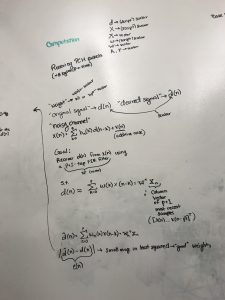
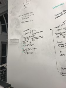
This week I actually went back to the enclosure design to edit the formation of the cans to better fit the new form of the PCBs. I also began implementing the RLS algorithm in Python with receiving PCM packets and removing generated noise. I struggled more than expected with the implementation, so I went back to the original algorithm and went over it in writing. This allowed me to be more clear on what I need to accomplish. My goal is to still complete this before the demo period on Monday, as well as add the models from Winston once they are all complete.
***
***
***
***
***

Winston:
This week, I focused on working on the layout of the boards, making sure that they:
- respect the dimensions set forth by Michaela along with reasonable placement of M4 screw holes,
- all PCB designs combined fit within a 100mm x 100mm square, for lower manuefacturing costs, and
- FPC, USB-C, and JST-PH connectors are arranged in a physically realizable manner, accounting for headroom for jumpers.
In terms of design decisions, I fused the previously top and bottom PCBs into one main PCB, which eliminated the need of FPC connectors and reduced the number of screw holes required. However, the trade-off in this decision is that the PCBs would take up more real estate. Fortunately, the four boards (namely main and side, left and right) still satisfy the second aforementioned constraint.
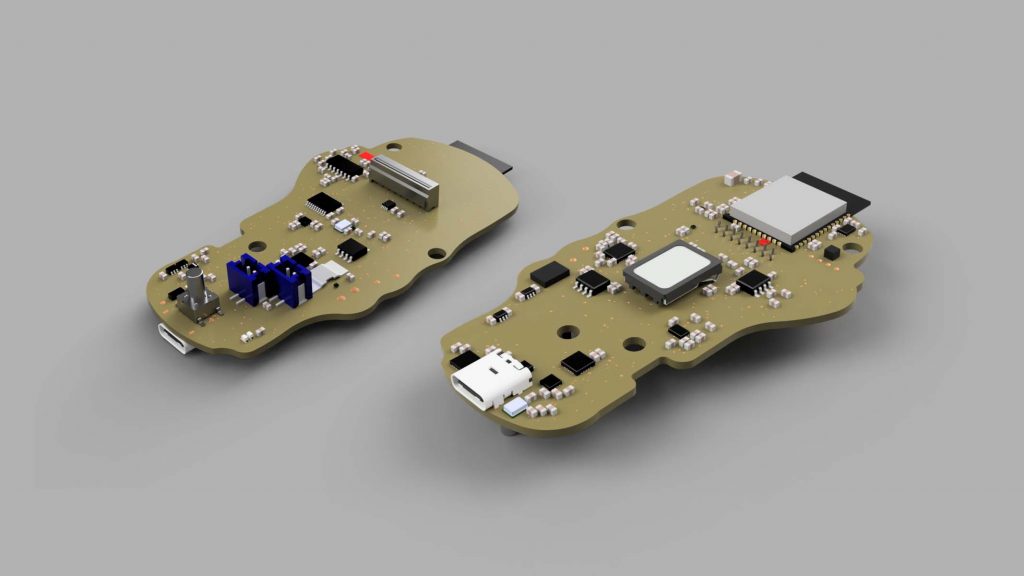
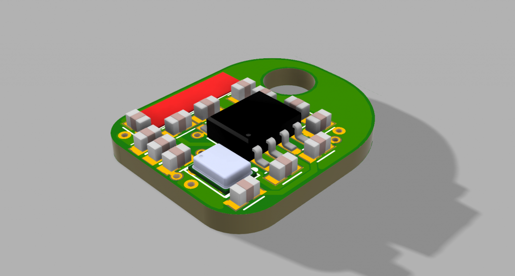
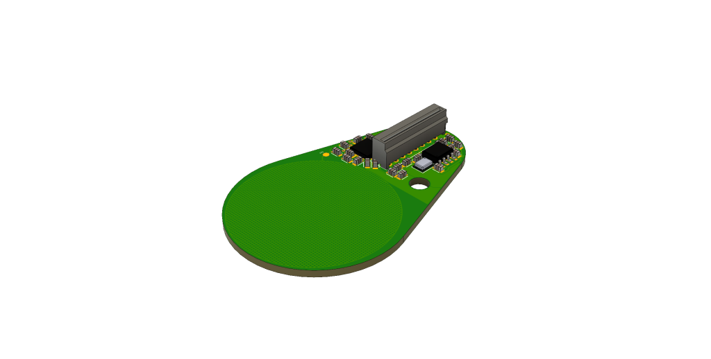
I also generated 3D models of the PCBs, utilizing the 3D models built previously.
I started designing the augmentation that needs to be made to the FreeRTOS event scheduler, which would constitute to our software architecture. I wanted to focus on implementing some of the firmware, but the team has agreed on the importance of our architecture and thus the switch in work priority.
I will focus on implementing the aforementioned architecture next week.
Team:
In terms of team work, we had a meeting with Professor Tamal to discuss our current schedule. Since we are behind progress, especially in terms of our PCB, we have come up with a Plan B in case it does not work or does not arrive in a reasonable time.
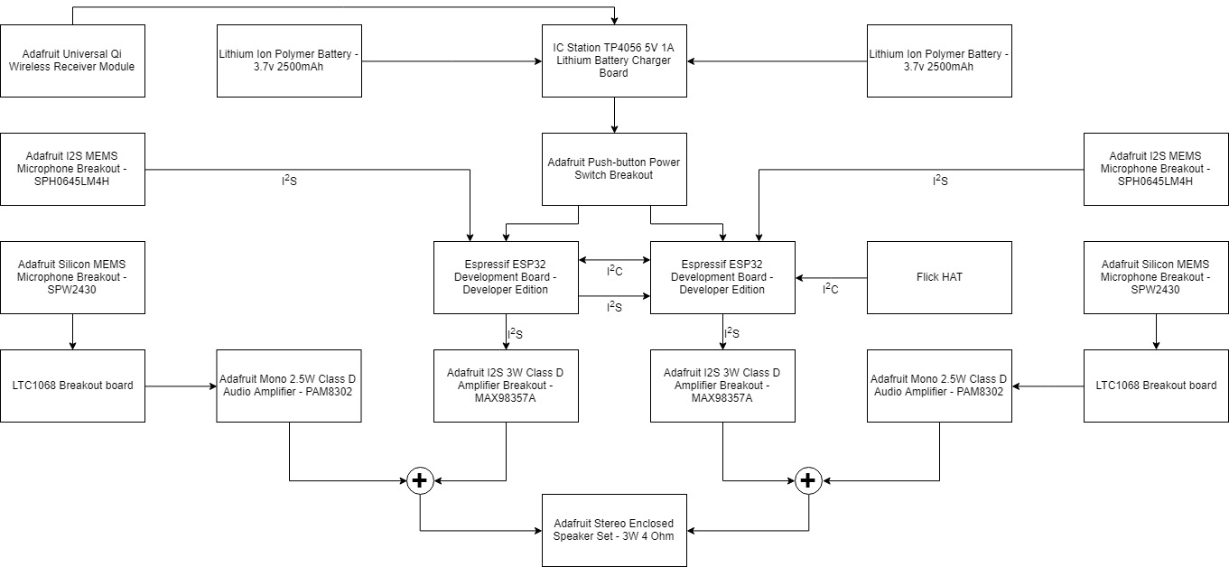
Below we have listed the outline for this plan, the ways it is different from our previous implementation, and the block diagram for this proposed plan.