Status Report 02-16 (szz)

Individual updates

  • Continued firmware bringup efforts that started in late January:

    • Worked with Deepak Pallerla and other CMR members to refine CAN, ADC, and GPIO drivers and their respective interfaces

    • SPI via DMA implemented and tested (below, left)

  • Designed high-level TOM system architecture by outlining required tasks and synchronization objects, including the radio API

  • Implemented and tested synchronized full-duplex SPI interface proof-of-concept

Schedule status

I am currently on schedule for my assigned tasks. Radio API design was at risk of falling behind due to missing XBee hardware earlier in the week, but they have since been sourced; I will have enough spare time this weekend to test out various configuration details.

Deliverables for 2019 Feb. 23

  • UART drivers brought up and tested

  • Radio API tested with XBee

    • Various Wi-Fi configuration/connection details must be ironed out

    • Full-duplex must be tested for robustness

  • XBee range tested

Status Report 02-16 (cmackint)

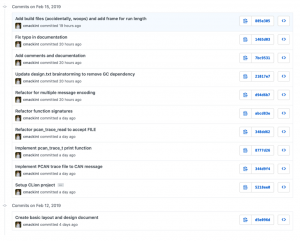
This week I worked on the CAN message compression codec. I tested various development environments: vim+Makefiles, Eclipse, and CLion+CMake, ultimately choosing the later. I installed and setup the STM IDE (TrueStudio) and the CAN capturing utility (PCAN Explorer) in a virtual machine. Stan and I captured a PCAN trace from the 2018 electric car; I will be using it to test CAN message compression algorithms. I wrote code to read these PCAN messages into a CAN message datatype.

I am no longer designing the codec entirely, and then implementing it. I have decided to test various algorithms concurrently. I am on schedule with the Gantt chart, despite.

I will complete by next week several codec compression implementations: run-length encoding, Huffman encoding, and the heatshrink embedded compression library. I will provide compression ratios for each of these implementations for comparison.

Team Status Report 02-16

The Week in Review

This past week saw promising progress being made via range testing, firmware bring-up, and PCB layout. We were able to pair and get data sending between two of our Wi-Fi transceivers, and had acceptable results during range tests at ~300 meters, with the help of two 9dbi antennae. This range result was still under our target for Wi-Fi range, so more testing will be necessary. As a fallback, we’re looking at inlining a Wi-Fi amplifier, putting a directional antenna on the base station side, and, in the worst case, sticking with one-way communication for reading car data

Risks

  • Complexity has been added to the design (from revision 0) by virtue of adding a second radio and splitting operation across multiple PCB’s and multiple radio transceivers. This complexity is not entirely trivial, and could cause system failure if details are overlooked.
    • To try and avoid these potential pitfalls, we will remain on the 2-revision timeline described in our proposal presentation.
    • Moving to a 2-PCB design will itself mitigate this complexity, by directly encapsulating system failure
  • The radio transceivers may have insufficient range. The cost of this is the inability to adequately communicate between the car and ground control application on race day. The following are proposed mitigations:
    • Transition from a omni-directional antenna to a directional antenna at the ground control
    • Use an on-board RF amplifier. This would require added hardware complexity (adding the amplifier to the RF path on the transceiver PCB), and will only be implemented if we can’t otherwise meet our range requirement.
  • Risks that have been resolved as of this week’s entry:
    • Basic schematic integration (Does the MCU/radio turn on and execute blinking lights firmware template?)
    • SPI communication on STM with the XBee radios

Design changes

  • Moved from a single board to a 2-PCB layout with 32-pin ribbon cable interconnect
    • Splitting the RF modules onto their own boards was necessary to fit into physical footprint constraints while keeping the board manufacturable and under cost
    • 32 pins provide plenty of flexibility, and the ribbon form factor gives spacing
      • Known unknown: EMI risks, with SPI at 3+ Mbps on a 5”+ cable
      • Sources indicate this should be tolerable, but we will keep an eye on it

Updated schedule

No updates: We’re on schedule in terms of PCB schematic and layout, as well as firmware bring-up and implementation. (See our Gantt chart for more details.)