Tucker’s Status Report for 2026-10-03
This week, we had our design presentation and continued forward with our schedule. In the near future, we need to order our PCB and complete our design report.
I spent quite a bit of time getting comfortable with the 68k instruction set this week, and what the PalmOS binary actually looks like. I spent some more time writing assembly in Easy68k. As an aside: it’s fitting that my version of Easy68k requires x86 emulation to run on my Mac.
I also built familiarity with disassembly and binary analysis of PalmOS. My tool of choice is Ghidra, though its 68k support is not as complete as other architectures. In particular, I found that its analysis tools regularly failed to run unless I manually entered function signatures. I identified utility routines including strcpy, a CRC16 routine, an entry point for a built-in debugger, and a lot of IO/MMIO. In reading the binary, I learned that I’d made an incorrect assumption while learning about the architecture: byte and word operations do not clear (or sign-extend) into the full width of registers, matching x86 byte and word registers, but not the x64 doubleword-to-quadword extension that I’ve programmed against more often.
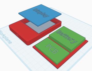
Work on the case will be useful for informing PCB design, and vice versa. I’ve developed an initial model where the display (with flex cable folded under) can be glued into the top of the case, and the mainboard and battery sit on a sled underneath. It helped develop a few constraints:
– The mainboard must go at the bottom of the device to make the buttons at the bottom work. (I’ve omitted the buttons from the screenshot below, because their placement will be defined by PCB constraints, but they’ll be top-hat style 3D prints that rest on the PCB buttons and can’t fall out of the case.)
– Therefore, the battery must go on top. The battery takes up the majority of the internal volume, as well as weight. The combination of display and battery on top is going to be heavy, and we may want to consider intentionally adding weight to the bottom of the case for balance and comfort, potentially at the cost of overrunning our intended weight limit.
– There is enough room for our LoRa antenna to reach around the battery to the top of the assembly. Despite the lower PCB placement, the antenna can be placed such that it won’t be obstructed by the body or left/right hands.
– The GPS IC will likely end up in a position where it may be obstructed by hands during use, since it must go on the PCB. Modulo EMI, testing with a piece of cardboard suggests that it will likely be least obstructed near the USB port, since there’s little reason for fingers to cover that area for extended intervals. I also considered whether we could place it on the back of the PCB, but that risks a prolonged obstruction by the palm of the hand.
– The USB port placement risks conflicting with button placement. However, we could place it off-center or extend the case out further.
Some factors that will depend on PCB design or upcoming team decisions:
– PCB mounting. I’d prefer to place drill holes on the PCB and add either self-tap screws or fully 3D printed pins into standoffs. I’ll have to experiment with pin and clip style attachments, as they seem preferable, largely due to straightforward reusability. However, screws are the simplest on the modeling side (add a ~4mm standoff with solid fill, and tap into it with a short screw).
– Backplane attachment. I modeled it as a plate that glues onto a recessed edge in the case, but this fails to meet our repairability goals. Screws would be difficult to fit around the battery and require more space above the display. We could implement a hinge, sled, or magnetic attachment. I’m slightly enamored by the idea of a hinge, and may prototype it; however, I think that the choice of mechanism is not a priority here, and a sled is a good backup (if potentially annoying to dial in on a 3D printer).
– Display attachment. I modeled it as gluing into the front of the case; this actually performs quite well for repairability, as it could be removed from behind with a heat gun or exacto knife. This is sufficient for a prototype. For a demo device, I’ll prefer to hide the edges of the display under the bezel, for both durability (protect the touch sensor) and appearance.
I made some progress on the emulator and instruction decoding, but no significant milestones here. That was an early goal, and my work on it will continue in the coming week.
Next week: our team is laying out the PCB, writing our design report, and keeping at software. I’ll be focused on emulator milestones this week. I also need to add a time to revisit the case design and do test fits to the schedule – TBD, but this will likely be a week or two after our PCB arrives.