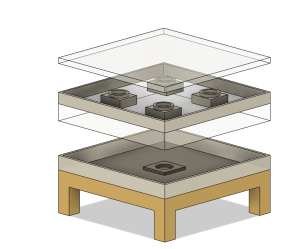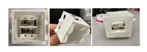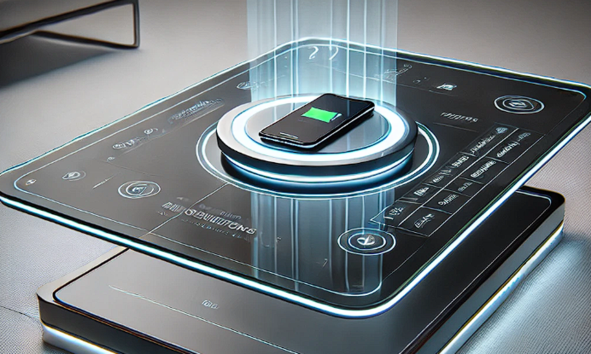
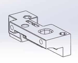
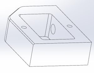
This week, our team successfully conducted the final presentation, effectively showcasing the significant advancements made in our hardware system. The presentation highlighted the structural improvements to the gantry system, particularly addressing the friction issues caused by the charging cable interacting with the charging pad connection. To resolve this, I enhanced our CAD model by increasing the distance between the glass interlayers on the tabletop by 2mm and redesigned the charging pad housing. These modifications ensure a better fit for the charging pad and prevent the cable from rubbing against the tabletop, thereby improving the system’s durability and performance.
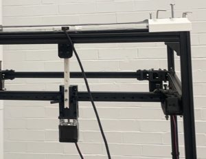
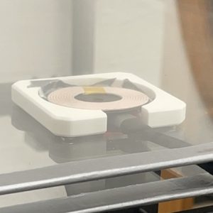
In addition to the structural enhancements, I dedicated considerable effort to unit testing and recalibrating the gantry subsystem. This involved fine-tuning the subsystem to accurately move specified distances in the XY direction and ensuring reliable interaction with the computer vision system. Moving from one end of the gantry system to another end, with 57 cm of travel distance, the average error rate for the system is about 1.8mm. We have also run several tests on Z axis manipulator and hardcode its value. Each time the travel distance of the Z axis has a 2-3mm error while trying to improve the stability, this margin of error is acceptable for the design.T hrough rigorous testing, we confirmed that the vision system accurately detects the coordinates of a cell phone and effectively directs the gantry to position the charging pad at the target location.
Looking ahead to next week, our focus will shift to further system integration and enhancing inter-system interactions. I will be collaborating with Bruce on state feedback detection and vision calibration for the gantry’s end effector, ensuring precise positioning after the charging pad is moved to its designated location. These efforts aim to refine the overall system functionality and ensure seamless operation across all components.
Overall, this week has been highly productive, with key improvements made to both the structural design and the functional integration of our gantry system. These advancements position us well for continued progress in the upcoming phases of the project.
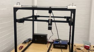
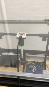
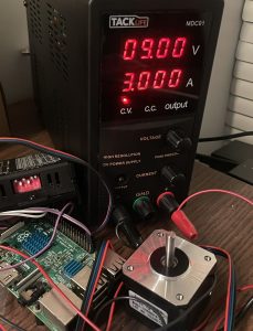
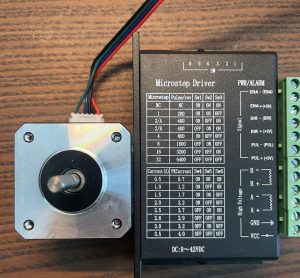
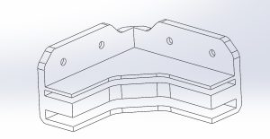
 My first priority this week was to complete the mechanical modeling simulation and part selection for the Gantry system. For the power configuration, I chose a common NEMA motor to power the system, a set of two motors to power the horizontal and vertical movement of the entire system, and a separate motor to control the arm up and down to grab the charging pads for movement. Since I hadn’t touched or designed a gantry system before, I researched and borrowed some designs from cheaper 3D printers, and used a combination of two sets of moving and fixed pulleys and 6mm belts for the drive, as well as a set of MGN9 rails for the limit. I finished picking and filling out the drivetrain parts on the purchase list and we’ve submitted it to the TA for review. Since most of the parts are being purchased using Amazon, we hope to complete the development of the motor controller drives and the basic Gantry build over fall break and the following week.