The work I finished for the past week is described as below:
- Center part design/printing/purchasing/assembly
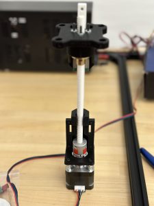
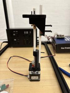 Assembled center part. Contains stepper motor, base, shaft, rail, upper part. The rail and the shaft are printed. Steel made rail and shaft are ready for cut (will be performed in machine shop). The upper part (primarily for charging pad attraction using magnets and movement) can move up and down on the shaft. Video was taken. This part is fixed onto the center manipulator as shown below:
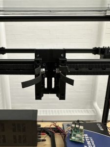
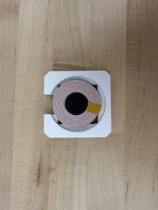
- Charging pad (charging pad was reprinted two times before it can work as intended) Steven will show in detail regarding charging results.
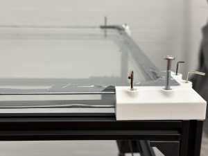
- Acrylic boards are replaced by glass boards and are fixed to the top of the table. Corners are reprinted to make sure they matches with the size of the glass board as well as the height of the charging pad
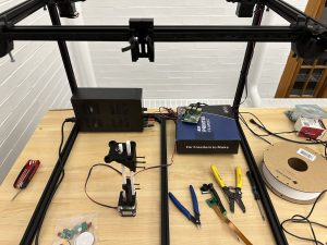
- Whole system overview with motor drivers fix into a box.Power supply under the table. All hardware parts completed. Assembled and tested for many times. Gantry runs good with odometry, can operate in all x, y and z axis. Center manipulator can drag charging pad around using magnets.
- System integration already began. Camera control gantry movement. Bruce will update on this.
Tools and knowledge needed to accomplish these tasks:
- Mechanical design skills
- Understanding of Rpi programming logics (eg: gpio),
- Gantry system principles
- Testing and troubleshooting methods: hw, sw, meche, external force
- Quick 3d printing skills
- system integration skills, how to connect sw, hw and meche together. How to control the subsystems.
learning strategies
- Online documents blogs for Rpi use
- Online videos for specific motor driver use
- Rpi/Motor/Motor driver operational manual
- Consult other students, professors
We will continue system integration and work on slides.