Bruce’s Status Report for 11.2

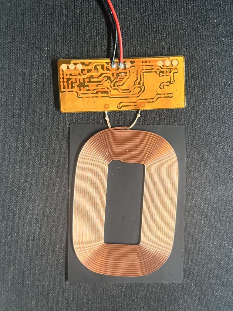
This week, my main focus was the development of the charging module. I worked on the integration of the charging pad with the Jetson Nano, our project’s central processing unit. By the end of the week, I successfully incorporated the charging pad with the Jetson Nano.

One of the key metrics I measured this week was the charging efficiency of the system. With the current setup, it takes approximately 45 minutes to fully charge an iPhone 13 Pro.  Currently, the charging pad is not stable enough, which means that sometimes it just suddenly stop charging the devices. I haven’t figure out the reason yet, so I am going to focus on solve this next week.
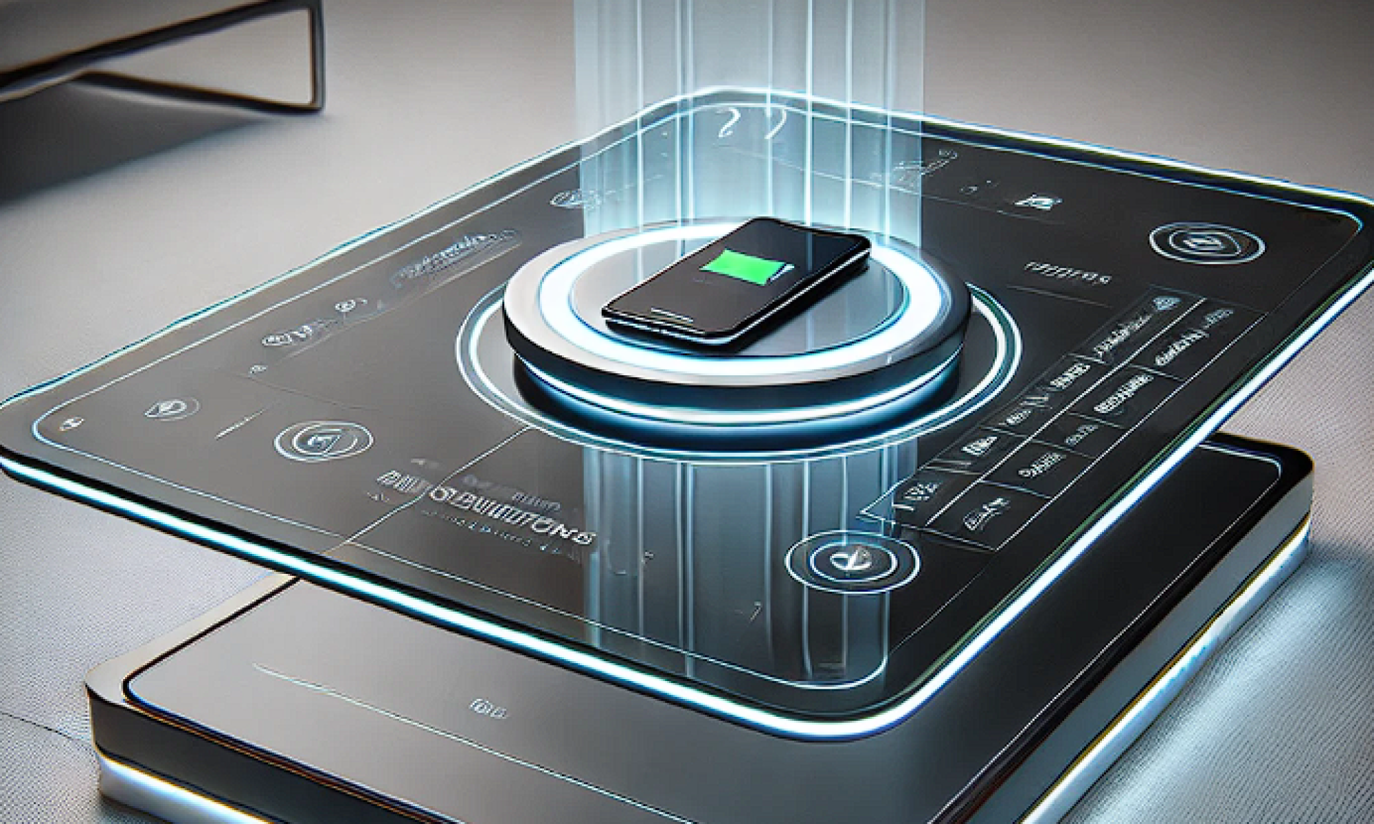
One big consideration was the unique structural layout of the table. The design must accommodate both the moving parts of the gantry and the magnetic properties of the charging pad without interference. Through testing, I discovered that certain materials and structural arrangements could impact the strength and stability of the magnetic field around the pad. I adjusted the layout and experimented with different materials to mitigate this issue, but further refinement will be necessary as we move toward finalizing the design.

I am currently on schedule.

In the upcoming week, the primary objective will be to improve the stability of the charging pad during the charging process.  I will also begin to build the gantry system to make sure we have enough time to finalize the project.
Steven’s Status Report 11.02

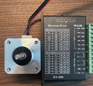
This week, my main focus was motor development. I successfully configured the motors on the Raspberry Pi using an external power supply to be able to perform basic commands such as turn and stop. Given that the Nvidia Jetson Orin Nano utilizes the same GPIO libraries as the Raspberry Pi, we were able to extend the motor control functionality to the Jetson platform, facilitating seamless integration with the motor driver. This compatibility provides a streamlined path for us to continue development on Jetson.

Despite these advances, I still need to accelerate the completion of the gantry system. It is important that we complete this work as soon as possible because it will allow us to translate coordinate positions directly into motor commands. This capability is critical to achieving the precise motion control we need for our application.

On the assembly side, Harry and I collaborated on the 3D-printed parts of the gantry and have made significant progress in building the structure. Next week, we plan to complete the assembly of the gantry system for functional testing. This phase will involve validating and assembling the mechanical design and ensuring consistency with the motor control logic. It is important that we complete the build and commissioning of this system as soon as possible, as we have created a partial gap between our process and our plan.

In addition, since the motor is the only component in our system that requires a high voltage range of 15V to 45V, we must determine the best way to fully power it. Our main challenge was to find a power solution that could be centrally managed to ensure operational safety. This required selecting a power supply or battery management system that could interface with our controllers, allowing us to safely monitor and control the power supply to the motors.

Harry’s Status Report for 11.02

This week I primarily work on the structures of our charging table. On Monday and Wednesday, the last few parts we ordered arrive so we could have a clear view regarding the components we purchased.  I examined the aluminum extrusions that will be used to form the frame of the table then studied on parts that could connect them. I used Fusion 360 to draw out some important parts as described below.

  1. Table upper corner: this part is used to hold the two transparent thin layers(either  acrylic or glass)   This component had already been submitted for printing at TechSpark on Thursday. We will gather the four pieces on Monday for further testing.
  2. Transparent layers side holder (further support two layers)
  3. Charging pad holder (will place the coils inside the groove and on the bottom of the charging pad holder will have magnets that allows connections with gantry system) 

3. Bottom corner


Overall, our progress is on time. Next week we will continue to perform on testing on difficult mechanical parts and consider parts that may not be good to be printed. We will then purchase them online. We will build the structure as fast as we can. Electronic parts testing will also go on.