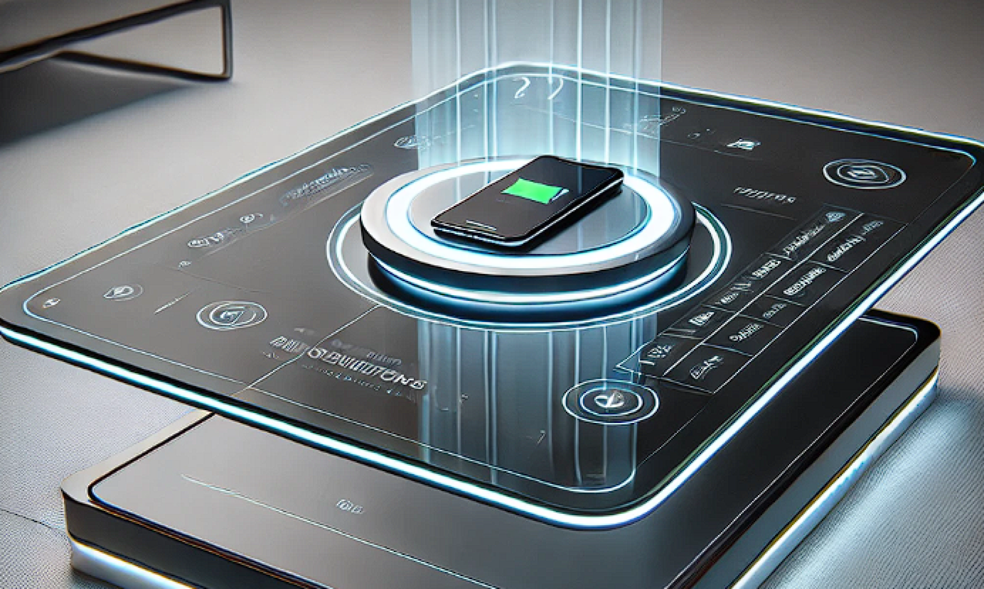
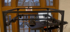
This week, my primary focus was assisting Harry in developing the overall framework of our project. Together, we dedicated a substantial amount of time to completing the mechanical hardware build for our automatic charging table. By utilizing aluminum extrusions, we were able to construct a sturdy and reliable platform that not only supports data acquisition an
d machine vision training but also maintains the necessary strength and durability required for our operations. The modular design facilitated by the aluminum extrusions allows for easy adjustments and future scalability, ensuring that our framework can adapt to evolving project needs.
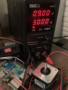
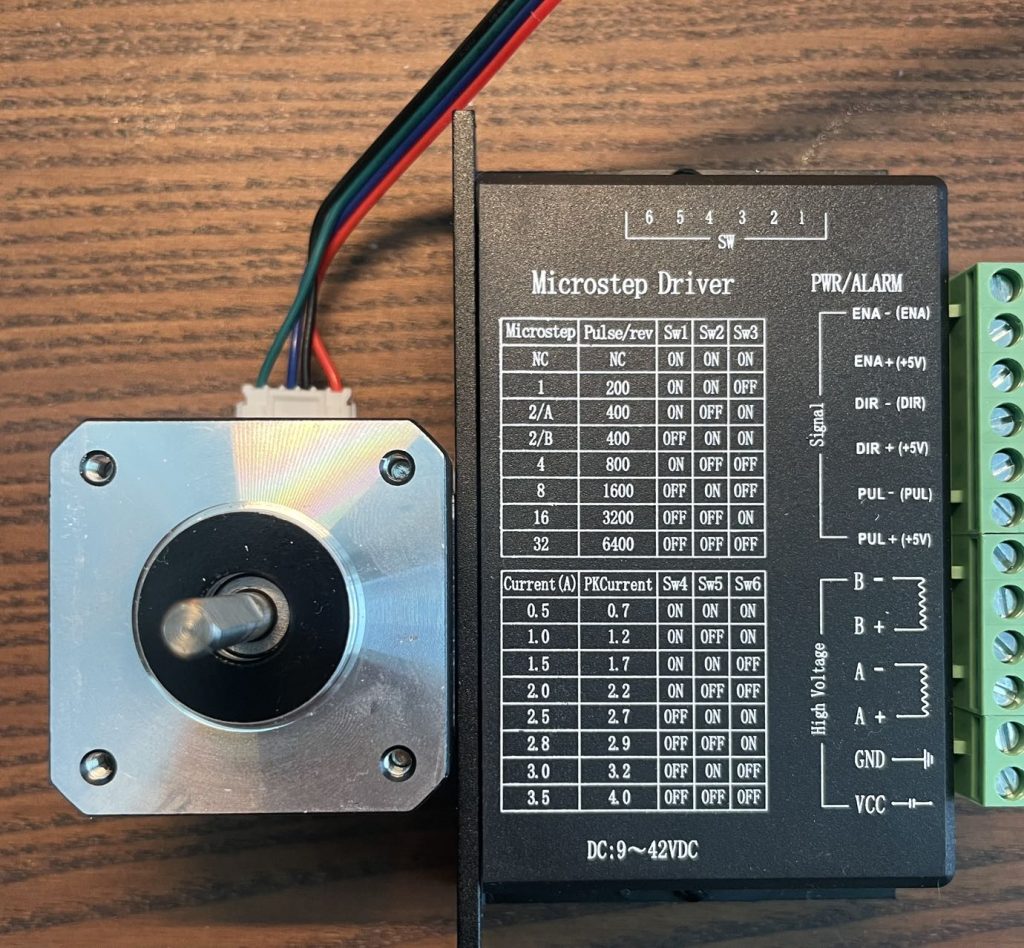
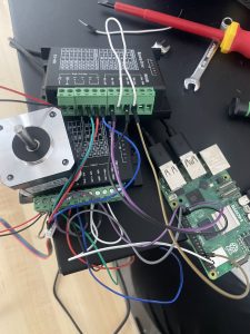
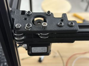
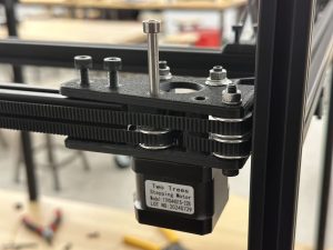
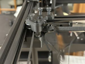
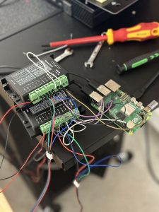
In addition to the mechanical advancements, I made significant progress on the gantry system, particularly concerning the stepper motors. I enhanced the motor control code by integrating motor drivers with a Jetson Orin Nano, which improved the overall functionality of the system. A key achievement this week was the successful conversion between the step size of the stepper motors and the corresponding belt travel distanc
e. This was accomplished by constructing a simple prototype of the gantry system, which served as a proof of concept for our control mechanisms. Furthermore, I tuned a set of Proportional-Integral-Derivative (PID) controllers to achieve more precise motor control. As a result, the motors now operate with increased accuracy, maintaining an error
margin within 5 millimeters over a 30-centimeter distance. While this level of precision meets our basic control requirements, it highlights the need for further adjustments to the control program to achieve higher precision for more demanding tasks.
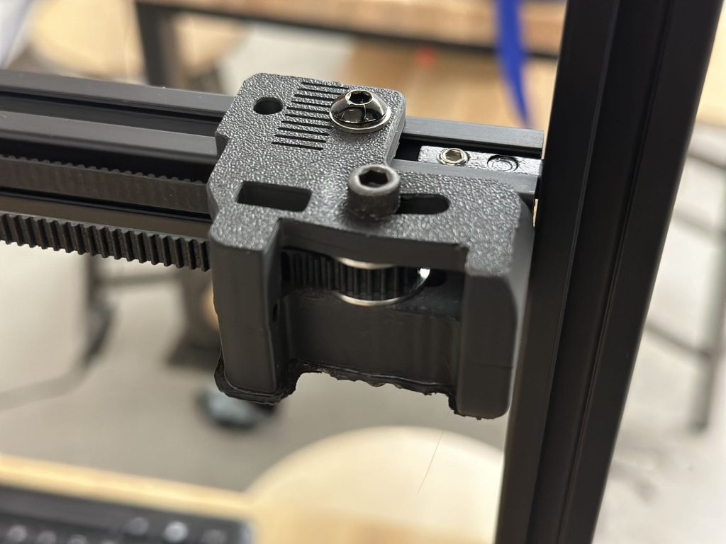
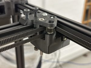
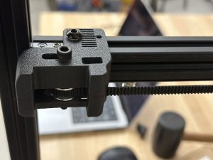
Looking ahead to next week, our plan involves mounting the gantry system prototype onto the main frame. This will require the use of 3D-printed parts to securely fix components such as the motors and belt gears. Ensuring that these components are firmly attached and properly aligned is crucial for minimizing vibrations and misalignments during operation. Once the prototype is mounted, we will conduct comprehensive performance tests on the actual frame to assess the system’s stability, accuracy, and reliability under real-world conditions. These tests will provide valuable data for identifying any sources of error and areas that need improvement in both the motor control algorithms and the mechanical setup.
Simultaneously, I will continue refining the motor control program to enhance precision further. This includes fine-tuning the PID parameters and exploring advanced control algorithms that can reduce the existing error margin. Additionally, integrating more sensors or feedback mechanisms may offer real-time data, allowing for more accurate adjustments and control. Maintaining effective communication with team members remains a priority to ensure cohesive progress across all project aspects. Efficient resource management, including the allocation of materials for the mechanical build and computational resources for code development, has been instrumental in our advancements this week.
In summary, this week has seen substantial progress in both the mechanical and software components of our project. The completion of the automatic charging table’s mechanical build and the advancements in the gantry system’s motor control have established a solid foundation for the upcoming integration and testing phases. Addressing the current precision challenges and continuing to refine the control algorithms will be essential in enhancing the overall performance and reliability of our system in the weeks to come.

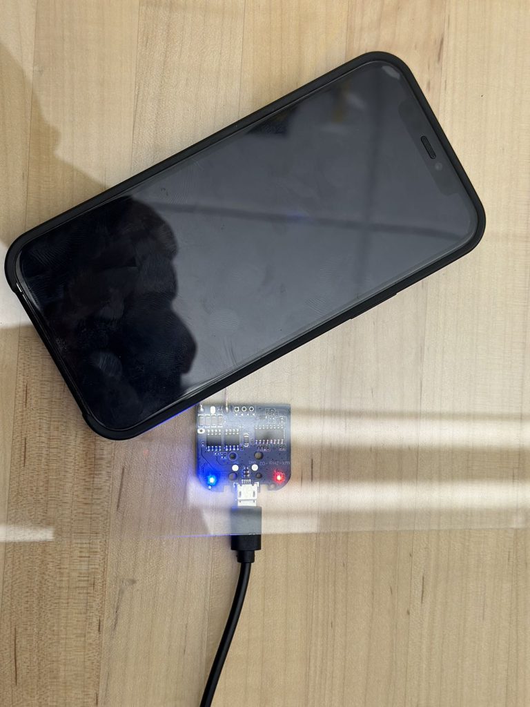
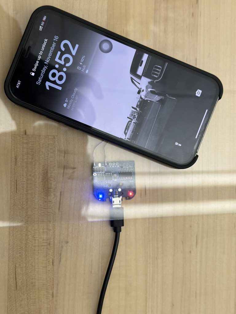
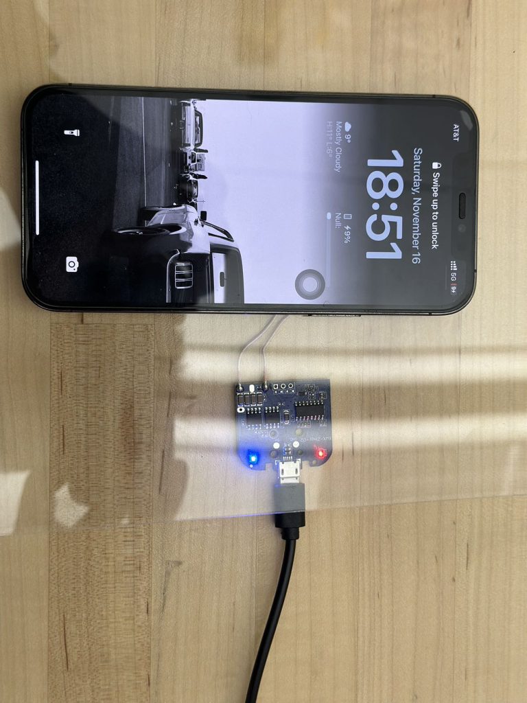

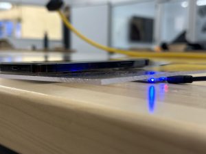
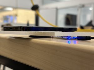 3mm board:
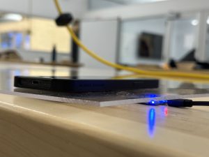

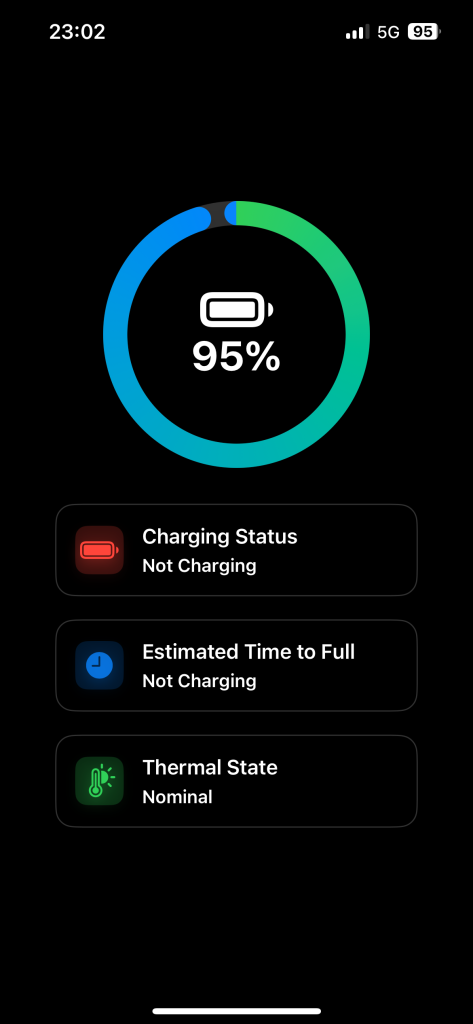
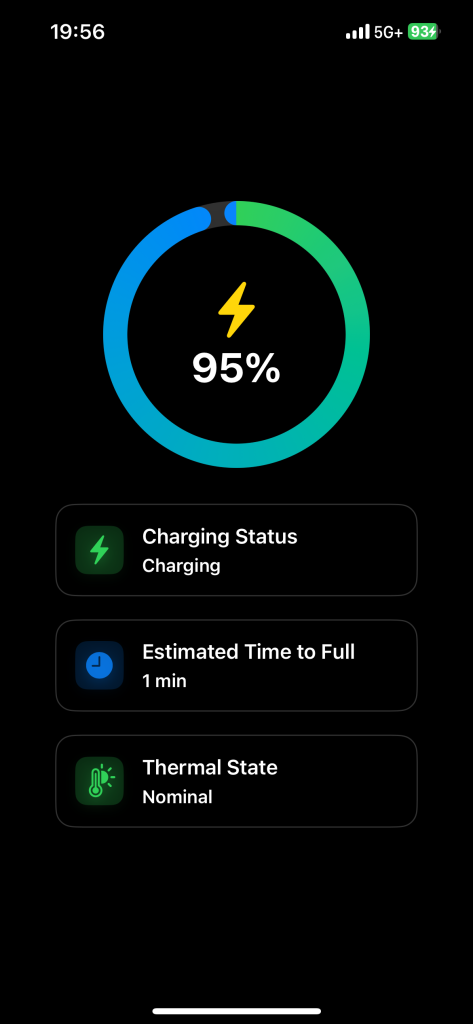
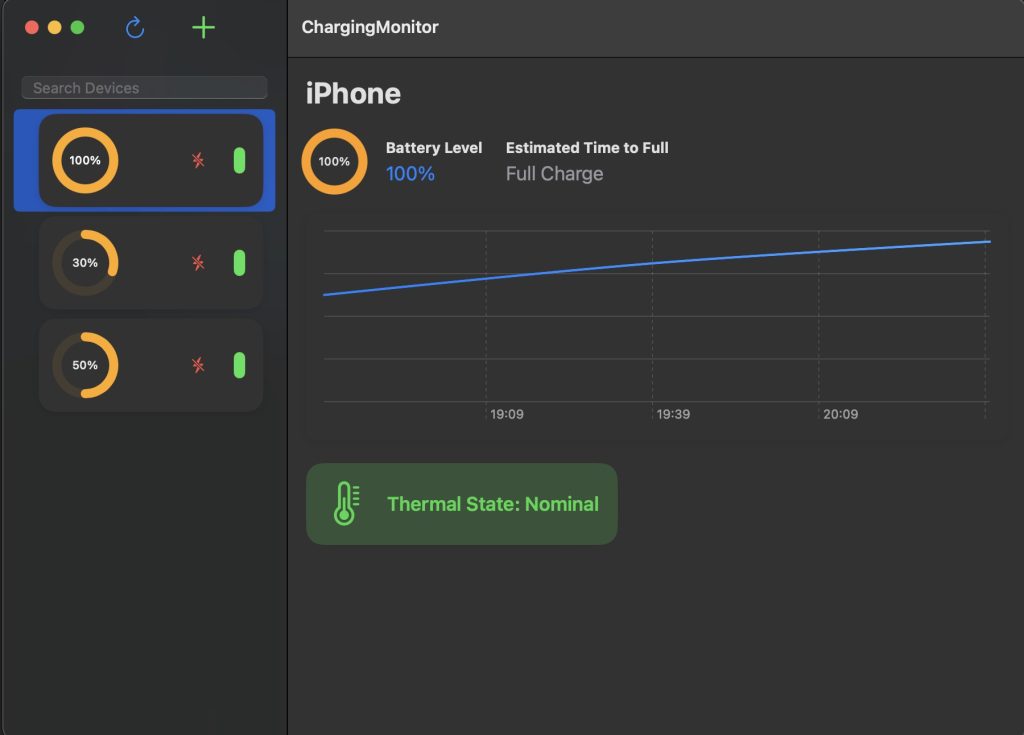
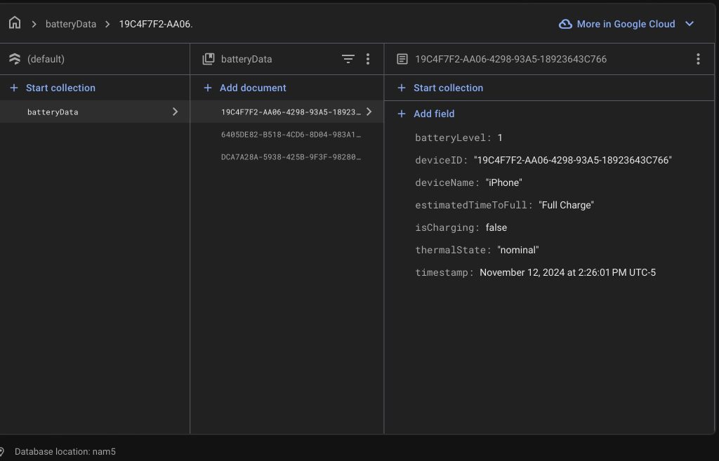
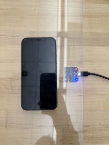
 This meets the design requirement of successful charging. Further data will be obtained regarding the time to fully charge the phone.