Here is what we did this week:
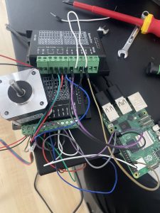
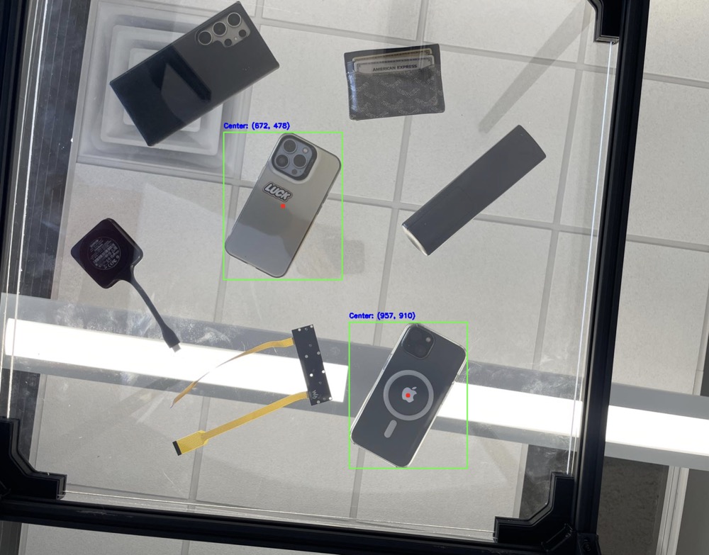
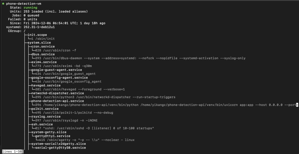
To optimize the YOLO-based object detection system, we migrated its operations to a cloud-based platform, creating an API endpoint. The Raspberry Pi now sends cropped images of the table area to the cloud for processing, reducing local computational delays. This change allows the Pi to allocate more resources to other critical tasks, such as feedback control for the charging pad and gantry system. After testing the cloud service 30 times, we observed an average detection time of 1.3 seconds and maintained an accuracy rate of 90%. These results met our requirements.
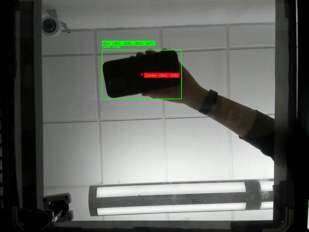
We improved the vision detection workflow by modifying the coordinate mapping system to align with the cropped images. Testing the gantry system under the updated configuration showed a consistent alignment precision within 1.5 cm across 20 trials. These adjustments reduces data size and improving accuracy.
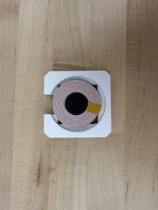
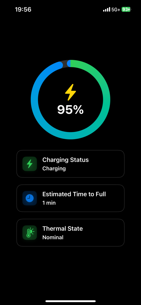
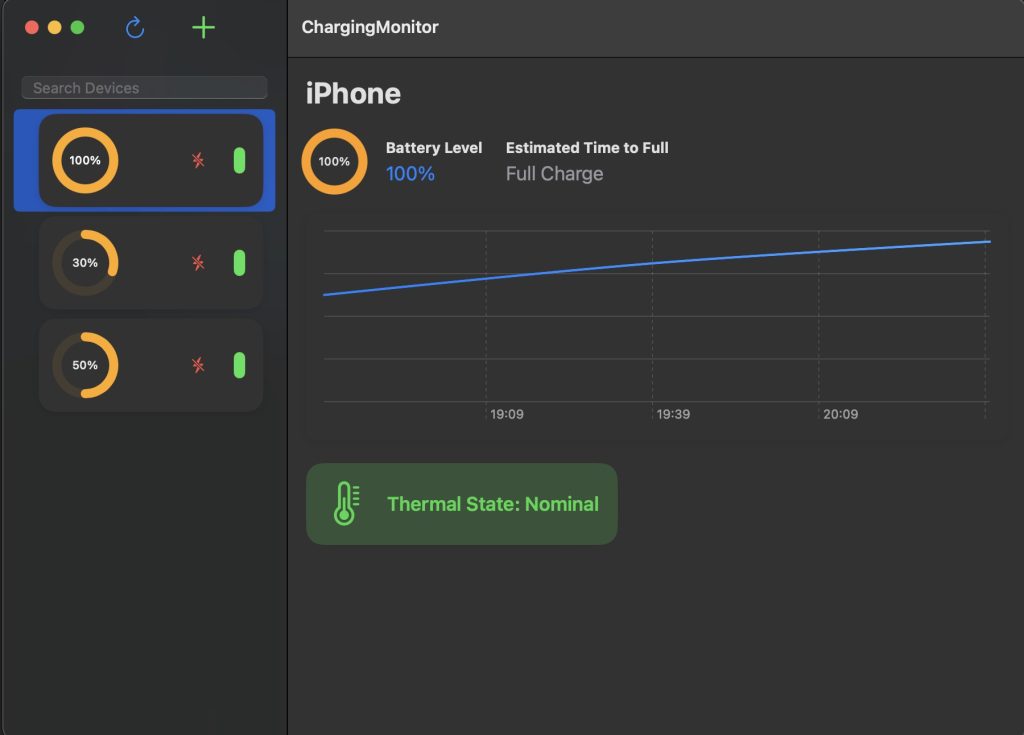
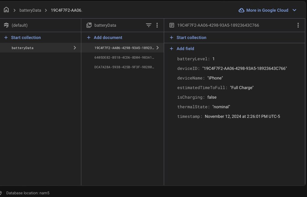
In terms of feedback control, we explored using computer vision to detect the charging pad’s light as an indicator of charging status. This approach provided faster and more reliable feedback compared to the app-based system, which suffers from delayed polling rates, especially in the background. Testing the light-based feedback on 10 images yielded a 90% success rate, with one failure due to improper HSV threshold settings. Adjustments to the threshold values are planned to improve reliability further.
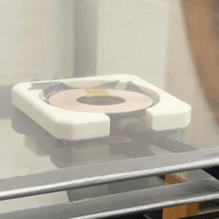

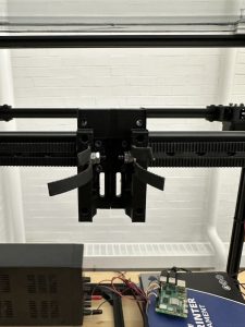
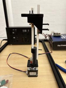
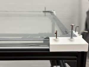
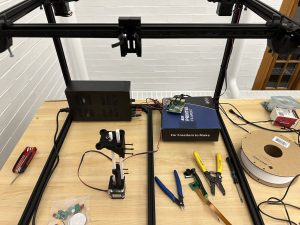
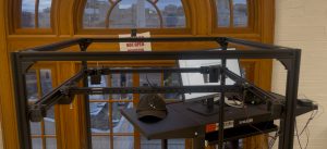
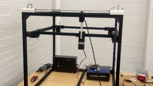
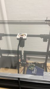
On the hardware side, we addressed stability issues with the gantry system by replacing PLA components with steel rails and shafts. These changes, along with revised screwing methods, enhanced the stability of the center manipulator. To resolve cable interference issues, we increased the height of the charging pad and adjusted the distance between the glass layers.
System integration tests were conducted to verify end-to-end functionality, including phone detection, gantry movement, and charging activation. While the system worked as expected, minor adjustments to ensure precise positioning are ongoing.
Looking ahead, we will focus on finalizing system integration and refining the interaction between software and hardware components. Specific tasks include tuning the gantry’s tracking and alignment feedback mechanisms and completing documentation, including a video, poster, and final report.
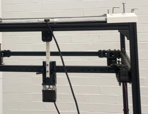

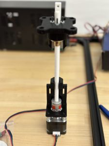
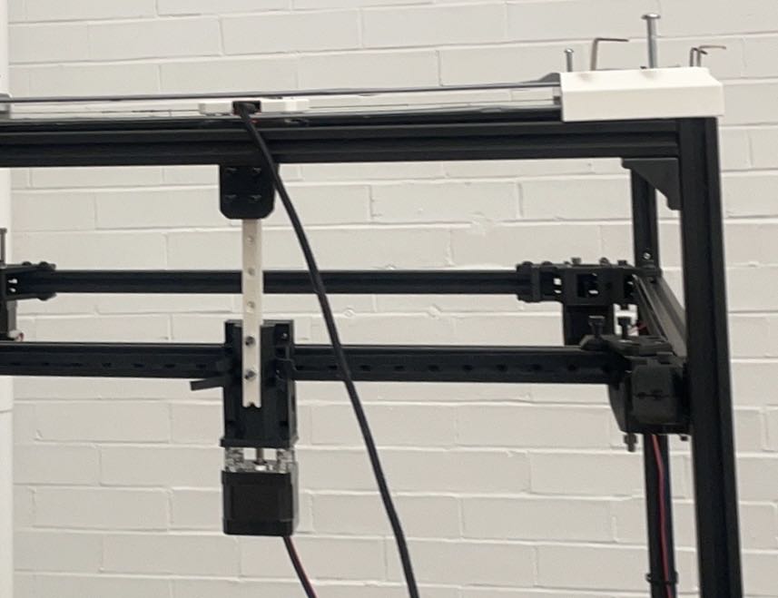
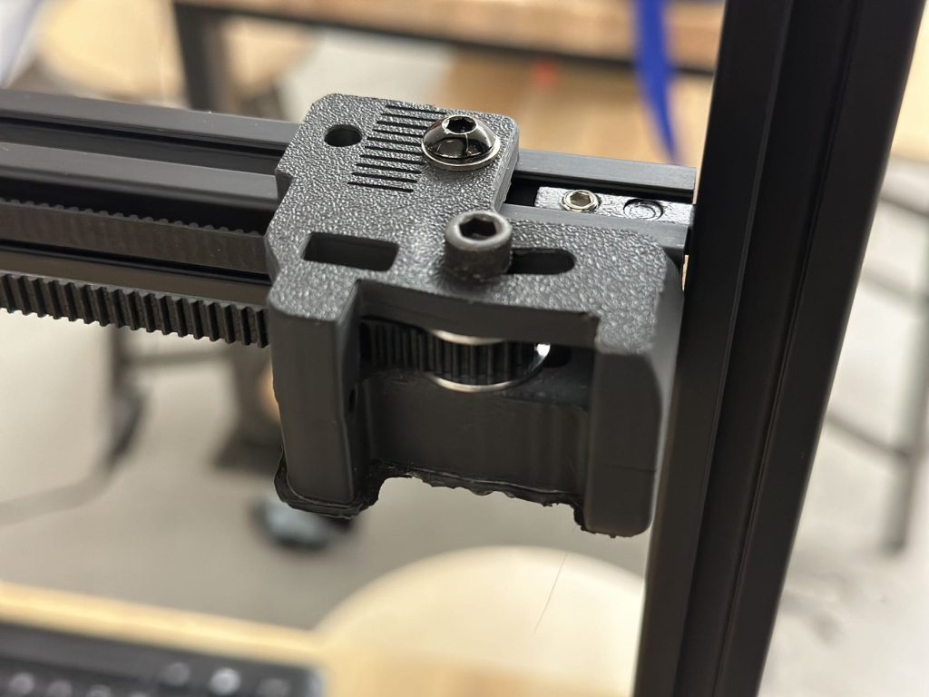 The problem that led to slow and uneven movement of the belt is the deformation of this 3d part. We reprinted this 3d part using ABS and it can then move on all x, y and z axis