Becky’s Weekly Post for 12/2

What’s new?

  • PCB did work, had a power issues 🙁 Could just be a one off mistake, but didn’t want to waste time debugging  because we were having more fundamental control issues with A4988s
  • A4988 motor controller were cumbesome, had issues going both directions, switched to l298N, easy to control, resolved issues at the cost of 4 pins on arduino as opposed to 2.
  • transitioned to a module based circuit design scheme, which has made it easy to get hardware up and running, and also help isolate power features of design, as well as trouuble shoot circuitry because we can isolate what we know works from what doesn’t. This circuit format is less robust than a PCB but better for its ability too iterate quickly.
  • Finalized Fundamental mechanical design for the most part
  • Got feedback on where to place registration tool from LAMP feedback session.
  • Decided to transition from using 4 solenoids to using 2 solenoids due to a combination of lack of IO/pins depending on how sensors are configured, and unexepected jiggling of solenoid stylus which loosens screw over time. Think this issue can be mitigated with lock tight
  • Learned about detent current, which can cause stepper motor to torque despite coils not being energized. Was worried we would have to get a new stepper which wouldn’t arrive until Friday. on a whim designed to power each coil to try to untorque motor, and it worked!
  • Made a test version of ir sensor
  • think we need to transition to LDR

What next?

  • Finalize and get light sensor working
  • tune vertical height on solenoids
  • mount braille directives
  • learn why detent current gets triggered sometimes

Becky’s Status report for 11/11

ABET #6 says … An ability to develop and conduct appropriate experimentation, analyze and interpret data, and use engineering judgment to draw conclusions

Now that you are entering into the verification and validation phase of your project, provide a comprehensive update on what tests you have run or are planning to run.  In particular, how will you analyze the anticipated measured results to verify your contribution to the project meets the engineering design requirements or the use case requirements? 

I’ve worked on the X/Y gantry system and the circuit design components of the project. The relevant requirements for me have to do with tolerances printing the braille and speed.

Mechanical Precision & Functionality: I will test to ensure that the placement of the gantry system allows for embossing, that the x gantry isn’t too close to the compliant surface. I need to test various compliant surfaces and select the best one. So far I have tested felt, styrofoam, and 1 grade of low density foam.

Usability: I need to test that our user can be able to determine which side the paper goes in quickly. I have created a texture that will be tested at this week’s LAMP demo, and we will get feedback there on its effectiveness.

PCB Testing: The PCB is set to arrive next week, and we will need to verify that it does all of the things we think it will do.

IR Sensor Placement: IR sensors are susceptible to reflective surfaces, so we need to do testing to see what position will not get bad signals from  reflecting off of the acrylic. This is important to our requirement tests because the IR sensor actually verifies that the paper has been placed in correctly.

Weekly Update:

I redesigned the PCB to be Arduino compatible given our team’s recent decision to switch the hardware over to be controlled by an Arduino, and communicate over UART to talk to the Raspberry Pi. The PCBs will be arriving just before Thanksgiving, so we will be able to test them during the break.

I ran into issues with the stepper motor circuit this week during demo. The current limiter circuit appeared to be not functional, and I did not have the tools I needed to do further testing during the demo.

Next week, I plan to build the Y axis component. I reached out to Zach from Ideate, and he will be bringing be a broken printer to take apart and get the rollers out of.

Becky’s Weekly Update for 11/4

This week I met with a mentor to discuss the loading system for the embosser, so we can finally order parts. I testing a few compliant surfaces and found that felt mounted on styrofoam would be  a great surface to print on.

I made some modifications to the loading system which include sensors to help determine where the paper is on the y gantry system, and side panels to ensure the paper is registered correctly.

I also realized that controlling all of this hardware with the raspberry pi may not be the best idea, because a lot of hardware controls tend to act pretty fast, and theyre may be latency introduced by having software and hardware processes done all on one unit

Becky’s report for 10/21

ABET #7 says: An ability to acquire and apply new knowledge as needed, using appropriate learning strategies

As you’ve now established a set of sub-systems necessary to implement your project, what new tools are you looking into learning so you are able to accomplish your planned tasks?

I am using Eagle CAD to design the PCB’s for the final project, and Fusion 360 to CAD the mechanical components of our project.

What did you personally accomplish this week on the project? Give files orphotos that demonstrate your progress. Prove to the reader that you put sufficient effort into the project over the course of the week (12+ hours).

This week I worked on the design report, and I finished up ordering parts for the X gantry, and started designing the PCB for the project. There was a lot of stuff I needed to import so I had to make sure they lined up to the A4988 stepper drivers we already purchased. Since EAGLE didn’t have the parts, I had to carefully source libraries.

Here is the schematic, the PCB will be routed next week.

Progress and Deliverables

This week I didn’t get as much done because we were on break 🙂 I plan on getting the PCB sent out on Tuesday to Flash PCB, and they are willing to manufacture our stuff faster, so we should hopefully have it back in a week.

This week I plan to send out the PCB to get manufactured, and get started making the X/gantry system. I want to tweak the y gantry this week, but that probably wont happen until this weekend.


Becky’s Weekly Status Report for 9/23

What did you personally accomplish this week on the project?

This week I met up with Alycia to get feedback on the design direction we should be going in for the Braille embosser. I asked her about how she can distinguish between different sides on a box, because we will need to be able to load paper in a specific direction on the printer. She mentioned different way of adding tactile information like adding an arrow to where the embosser needs paper inserted.

She also gave us the opportunity to use her different accessibility tools on her iPhone, and I have to say I’m pretty impressed with how easy it is for her to navigate around on her iPhone with her braille input device. She was able to navigate around Wikipedia and search up information about Beyonce no problem. She also showed how certain menu displays are not accessible to her, and aired some grievances about the Dunkin Donuts app and their inaccessible app.

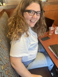
I learned so much from Alycia this week, and I think her involvement in the project will steer us towards making a project that is actually useful to blind users. She took the time to show us the different tools she uses in her day-to-day life and that gave us some ideas on things we can integrate into the software side of the project. Specifically, she showed us these glasses she uses to read text, and detect scenes, which integrate already into her phone and could be a cool tool to integrate into our project because she could take a box with instructions, look at it with her glasses, and then take the text output from the glasses, and convert it into braille. Here’s a pic of me trying these glasses on at Panera Bread this week.

Me wearing the glasses that read text and detect scenes.

I started exploring how the gantry system was actually going to get constructed, and realized very quickly that designing our own system from scratch would be really expensive in terms of time, effort, and money to create, and that it would be a better use of time to buy a x/y system that was already built. I ended up finding a 3D printer for 135$ on Amazon that would have all of the mechanical parts we would need to print braille, and most of the electronics already included. When I looked into 2D plotters they were more expensive, and also may not be the best choice because we want to be able to control the amount of tension we have between the paper and the embosser.

I think using the 3D printer kit would come with many advantages including:

  • X/Y mechanical movement already figured out (saves time & $$$ on prototyping)
  • Electronics have JST connectors we can plug into our control board for easy wiring
  • We can control the Z-height of the embosser, which will be good for finding optimal tension between the paper and the embosser. It also gives us a lot of flexibility when designing the embosser
  • Parts already integrate into the RAMPS based control system we plan on using.

Like any other decision, using this kit will have its’ drawbacks.

  • The z-height is much taller than we need it to be. We can cut this piece, but that will require us to disassemble and reassemble the x/z gantry
  • We will need to figure out a way to make it easy to register the paper (consistently place the paper in the exact same location)  in a way that is accessible to our user. I think we can accomplish this by creating a easy to use slot based system.
  • We will need to modify the slot where the extruder goes to fit the solenoid.

If we were to source our own parts, it would be so much more expensive to build, to the point where it wasn’t worth finishing the spreadsheet.

DIY assembly Cost Quan Total Link
Nema 17 motors 8.99 3 26.97
Linear slide + mount 37.99 3 113.97
limit switches
tensioner
t slot
Nuts & screws
T-Slot Brackets
ETC
ALT TOTAL 140.94

Using the 3D printer kit will take some work to modify. We will need to do the following to create a system that meets our requirements:

  • Creating a mount for the embossing solenoid to go on the X/Z gantry
  • Making an accessible registration system
  • Creating an enclosure for the 3D printer so it is safer to use
  • Integrate the electronics to the ramps board
  • Figure out how to control the solenoids on the ramps board
  • Figure out how to communicate with the software portion of the project

I started exploring how we will control the system as a whole, and there is a way to control the 3D printer using G-Code on the RAMPS board. We will be able to modify the firmware to meet our hardware needs, as they have a way to add solenoids. I think we will be able to also add a setting to keep the embosser head at a specific height, depending on the tension that works best for printing.

I also started exploring how to communicate with the RAMPS board over Wi-Fi, and there is this software called Octo-Print that runs on a raspberry pi can control a 3D printer. I will need to do more research to see how we can integrate it into our software system, but it is a good sign that this exists.

Is your progress on schedule or behind? 

I feel like I’m making good progress on the project, and I think this week we can actually make some tangible progress if we can get the 3D printer ordered this week.

What deliverables do you hope to complete in the next week?

  • Order the 3D printer kit, and RAMPS Controller
  • Put in a request for a raspberry pi
  • Come up with a specific plan to communicate with the 3D printer over wifi
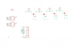
  • Design PCB’s that make connecting the limit switches, solenoids, and any other auxiliary hardware easy to plug into the ramps board.