Team Status Report for 9/30/23

The most significant risks that we are currently dealing with are the detection of which string is strummed and that the same note can be played with different fingerings.

We currently have a plan regarding how to detect the user strumming, although we do not have a method yet to determine which string was strummed. We have been brainstorming various methods to do this, all of which have potential. The first is performing capacitive touch sensing of the strings. This may be difficult though since the user may rest their fingers on the strings other than the one they are strumming. Additionally, the strings are already being driven by other signals so we would have to perform some sort of multiplexing on the strings to do this. We have also considered using COTS inductive pickups, although we have yet to find one that has an individual output for each string, which we need. One final method is to use a separate microcontroller with the sole purpose of sampling audio, performing an FFT, and sending this to the Teensy. The Teensy loop is likely going to be on the order of 100Hz, which means it cannot sample audio fast enough.

Regarding determining which finger placement to use, our current plan is to determine the physical distance between the previous note and the various finger positions for the next note, and choose the closest. This will involve creating a simple distance metric that the Teensy can run.

No major changes have been made to the system block diagram or implementation. One minor change is that we originally planned on using a 12V power supply along with a 5V buck converter. This would enable plugging in a 3S LiPo battery for mobile use. This was done to remove the need for a 5V 5A buck converter. In the future, if we would like to use a battery, we can simply add a buck converter with a battery connector on one side and a 5V barrel plug on the other side.

No changes to the schedule have been made

This week’s accomplishments:

  • Tushaar developed a state machine for the Teensy and decoded a MIDI file. He also has been able to run the NeoPixel library on the Teensy and control a series of 16 LEDs
  • Ashwin set up the RPi with Django and has hosted the webapp from it. The webapp currently has the ability to upload MIDI files and delete them. The Pi has been setup so it can be easily accessed via a2superfret.wifi.local.cmu.edu.
  • Owen has finished the design of the fretboard PCB and sent it out for fabrication. He has also created a circuit that can do strum detection with a fairly high accuracy, although this will need to be tested on the actual guitar
  • As a team, we ordered the guitar and discussed exactly what data and signals we want to send between the microcontroller and Pi

This coming week we hope to verify certain aspects of the guitar, such as the continuity of the guitar strings, the string spacing and fret spacing, and analyze the audio picked up by a microphone in the guitar. As a team, we hope to further refine the signals sent between the Pi and Teensy. We also hope to assemble the PCBs if they arrive so that we can begin writing to the LEDs on the boards and writing code to read from the frets.
 

Tushaar’s Status Report for 9/30/2023

This past week, I worked on 3 main things:

  1. Figuring out how the embedded software will work at a high level (state machine) – this involved knowledge from 18-240 for creating an FSM
  2. Getting started with the electronic hardware (Teensy4.1 and making sure I can individually address the LEDs) – this involved
  3. Figuring out how to parse a MIDI file – this involved lots of binary and hex conversion, a 15-122/18-213/18-240 skill

This is the proposed state machine for the embedded code:

Magenta shows inputs that originate as interrupts set by the RPI (teensy reads the input on its digital pins).

Red are inputs to the FSM originating from other parts of the microcontroller software.


I am able to address the LEDs individually:


I got a MIDI file from the web and manually parsed it according to the MIDI file standard to ensure I understood what we were working with. Here are my notes:

This progress is on schedule. I obtained a sample MIDI file by the time outlined in the Gantt Chart. I also procured a Teensy from Owen by the date we set in the schedule. The schedule says to be able to parse a MIDI file by Oct.8, and I am on track for that. We need to individually address each LED by Oct.15th, and I can already do that (but I will need to revisit this when the PCBs arrive).

Tasks for the next week:

  1. Give the Design Review Presentation
  2. Light up LEDs according to the frequency and timing specified in the MIDI file
  3. Implement a preliminary state machine in the embedded software

Ashwin’s Status Report for 9/30/23

In developing the design for our project. There was a significant software component that allowed me to utilize skills I learned from 17-214 principles of software construction and 17-437 web app development. Specifically, I knew that our web app would need a model-view-controller design pattern to help sustain maintainability and testability while isolating separate components.

After deciding on this, I spent time researching the best library for developing a web app and ultimately decided on using Django. This is a high-level web framework for Python that promotes rapid development and clean, pragmatic design, providing built-in features like an ORM, admin interface, and robust security, making it an efficient choice for developing maintainable web applications.

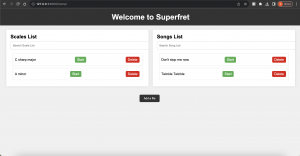
I created a GitHub repository for our codebase at https://github.com/ashwin-godura/18500-SUPERFRET, and started coding up the user interface. I developed a static webpage that visualizes how our users will interact with our device. This puts me on schedule with the development on the software side. Next week I hope to have most of the user-facing logic complete with the ability to add and delete files and start and stop songs.

Owen’s Status Report for 9/30/23

Weekly Question:

This week, the knowledge that I learned in the following classes aided my design process:

18320, 18623, and TAing 18100: These classes helped me understand the design considerations and techniques when building analog circuits. For 18320 and 18623 has helped me develop skills in hand calculating circuit performance, and 18100 TAing has given me experience in actually building circuits and making them robust. This was relevant primarily for designing the strum detection circuitry, which handles analog signal processing.

18240, 18320: These classes helped me understand the timing requirements and considerations when creating circuits with flip-flops, which we used in the design of the fretboard PCBs. This allowed me to understand the data given on datasheets for flip-flops, enabling me to be confident in the choice of flip-flop I made.

I don’t have any formal coursework in PCB design. However, for past personal projects and internships I have done PCB design. My experience in the past was with Altium and EasyEDA, but for this project I decided to use KiCAD. This was mainly done since KiCAD has become a very popular tool recently and I wanted to switch away from EasyEDA. I was mainly able to use my experience from previous design software to figure out how to use KiCAD, but I also found posts on KiCAD forums useful when learning application-specific keybinds and shortcuts.

This week, I finished the design for the fretboard PCBs and put in an order for the boards and the parts. The main changes to the design were the layout of the I/O pins, adjusting the spacing of the LEDs to match the guitar we are ordering, and adding a ground plane. The pinout was changed to make the PCBs easier to chain together without overlapping wires.

In addition to updating the PCB and ordering the parts, I also continued working on the detection of strumming in hardware. I have a design that currently functions on a breadboard but needs fine tuning. This will likely wait until next week when we have the physical guitar, as the tuning of values should be done for that system. The general processing done to the audio signal is shown below.

I have also begun the initial design process for the PCB that will house the microcontroller, strum detection circuit, buzzer for the metronome, logic level conversion for the LEDs, and power distribution. My current thoughts are to make a hat for the RPi. This will have the Teensy, a barrel jack for power, an active buzzer, and a handful of headers/pads to connect to the LEDs, fret sensors, and microphone.

I am currently on schedule. For next week I hope to test the strum detection circuit on the actual guitar. This will allow me to fine-tune the component values used for the circuit and ensure that the system will work. We have a fall-back plan of using the piezoelectric pickup that is built into the guitar. We can tap into this signal (or the amplified version) for likely a much higher signal-to-noise ratio signal compared to the microphone. I would also like to begin planning the general layout of the PCB, such as creating the general outline for the hat and the pin headers to attach the PCB to the Pi. If the fretboard PCBs come in, I also aim to begin assembly of the boards so testing can begin soon.

Tushaar’s update

I went back and forth with Owen about the strum detection. I have broken  down the embedded effort and identified  4 tasks:

  • LED signaling
  • Reading the frets
  • Detecting strum – this is currently identified as the hardest technical challenge
  • Interfacing with the pi – this will probably be UART


Owen’s Update: 9/23/23

This week I primarily focused on performing an initial analysis of various aspects of the design. This consisted of determining how well a microphone will be able to pick up low frequency guitar notes, developing preliminary circuits for detecting strums, and measuring the latency required to write to WS2812 addressable LEDs.

For performing preliminary tests on picking up low frequency signals, I connected various electret microphones to an oscilloscope and observed their output waveforms when measuring a low frequency guitar note played from my computer. I found that using microphone breakouts with 50-100 times gain was more effective compared to creating an equivalent amplifier stage external to the microphone. The immediate amplification of the signal on a breakout board helped to eliminate most of the 60Hz noise that was introduced when routing the signal to an external amplifier stage. As such, if we choose to pursue a microphone-based approach, using a board such as Adafruits Electret Microphone Amplifier – MAX4466 with Adjustable Gain would be a good option. I did observe that low frequency notes were often drowned out by external noise and movement, which will significantly increase the complexity of a microphone-based approach for detecting strumming.

One observation I quickly made was that detecting a ~40Hz note in around 40ms using an FFT would be nearly impossible, since less than 2 periods of the signal would be collected. Additionally, measuring high frequency signals would require that the microprocessor is constantly sampling audio, which would take its attention away from driving the LEDs and talking to the Pi. As a result, Tushaar and I agreed that some amount of processing must be done on the analog side first. I experimented with various potential solutions and have had success with a 1st order low pass fed into an envelop detector, which is then fed into a differentiator circuit. The output of this system is a voltage spike that corresponds to sudden increases in the amplitude of sound waves. This would then be read by an interrupt on the microcontroller. This circuit has shown promise, but it will still detect sounds such as claps and output a signal. I hope that by putting the microphone in the resonant chamber of the guitar, or by tapping into some guitar’s built-in string pickup system, we can increase the signal-to-noise ratio of the system.

I also ran some basic tests on a strip of WS2812 addressable LEDs. From my testing I determined that writing to the ~56 LEDs that we will have should take around 2ms, which puts an upper limit of 500Hz on how fast we can sample audio signals.

This week I also worked on the design of the fretboard PCBs and picked out parts for them. They are mostly complete pending some slight sizing changes in order to best match the LED spacing to bass guitar string spacing. I hope to order the preliminary round of boards sometime this week. The design is made to be easily daisy-chainable. I decided to run two sets of power lines, one for the LEDs and one for the flip-flops driving the frets. I did this to avoid any ground-loop issues being caused by the voltage drop along the LED power wires. This does increase the number of wires that will be on the fretboard however, so it may be worth looking into consolidating for the final PCB run if this proves to be too many wires for comfort. The schematic and PCB were made in KiCad. I have not used KiCad in the past but I decided to make the switch to it due to the larger user community compared to my previous EDA tool.

Team Update: 9/23/23

One of the primary concerns brought up regarding the SuperFret project is that the metal frets of the guitar will be driven to 3.3V. When the string contacts the frets of the guitar, they will be driven to 3.3V as well. Since the user will be in contact with the guitar strings, concern has been raised regarding the system’s potential safety hazards. Fully understanding any safety concerns with our project is our number one priority, since as developers of a product, we have no right to put users in the way of any degree of risk. Users of the system may be unfamiliar with regulations and standards regarding safe voltage and current levels, so it is our job as designers to ensure that all safety considerations have been addressed.

Before ever selecting our project topic, we fully considered the risks to the user and determined that they were non-existent. In the time since selecting our project, we have further researched this topic to confirm the conclusion that putting 3.3V on the strings poses no safety risk.

According to  IEC 61140:2016, Extra-Low Voltage is defined as less than 50V RMS for AC signals and less than 120V for DC signals. The IEC defines Extra-Low Voltage signals as having a low risk of electrical shock. The IEC further defines the Safety/Separated Extra-Low Voltage classification, which is used for voltages so low that even in the event of a system fault, there is no risk of electrical shock. To fall into the SELV category, systems must not expose users to voltages of 60VDC or higher for more than 200ms. Our intended solution for applying voltages to each fret will consist of pulses of 3.3V measured on the order of tens of microseconds, meaning our system would fall into the SELV classification.

Additionally, OSHA 1910.303(g)(2)(i) states that voltages above 50V are to be considered hazardous, with very rare reports of burns resulting from 12-24V car batteries. All incidents reported by OSHA 1910.303(g)(2)(i) at these voltages resulted from the voltage source coming into contact with a ring or watch worn by the user, and were at voltages 3-4x what we will be using. As such, we are confident that by requiring users to not wear any metal watches, rings, or bracelets, there is no risk of shock with our system.

For our proposal, we required that in dry conditions, our system falls within the IEC TS 60479-1 AC-1 classification, which defines a signal that is imperceptible to humans. This requires a current under 0.5mA to flow through the body. Dry skin typically has a resistance of at least 50kΩ, although assuming a worst-case scenario of 10kΩ, this will correspond to a current of 0.33mA flowing through the body. In wet and/or sweaty conditions, we will require that our system adheres to the IEC TS 60479-1 AC-2 classification, for which signals are perceptible but do not affect muscles. This classification requires under 5mA of current for continuous signals, although we will limit our system to 1mA worst case. To do this, we will put a 3.3kΩ resistor before the 3.3V signal connects to the fret, meaning that no more than 1mA can flow through even a direct short circuit. By doing this, we are confident that our system will pose no risk to safety.
File:IEC TS 60479-1 electric shock graph.svg

Other factors that we considered were environmental and economic. By requiring permanent modifications to the guitar to be made to install our system, we must not unnecessarily increase the waste of resources or money. This was one of the many considerations that led to our requirement that the guitar should still feel and play normally when the system is not in use. Although the system will modify the guitar, the normal functionality will not be affected, and therefore if the user does not want to use the system, there is no need to purchase another guitar. While a removable system using a flexible PCB that spans the entire fretboard may be possible, to reduce excessive design risks, we decided to steer away from this option in favor of smaller modular PCBs spanning the guitar.

In addition to working on our project proposal presentation and trying to consider as many aspects of our project as possible, this week we worked on acquiring a Raspberry Pi from the ECE supplies and researching guitars. We were worried about picking up strumming from ambient noise, but in our research, we learned that many electro-acoustic guitars use piezoelectric pickups at the base of the strings to directly measure the vibrations of the strings. Getting a guitar with this system and tapping into the output of the piezoelectric sensor will likely provide us with a signal that is significantly more resistant to external sounds and movements. We hope to finalize our decision this weekend on a guitar so we can progress further with preliminary testing and implementation.