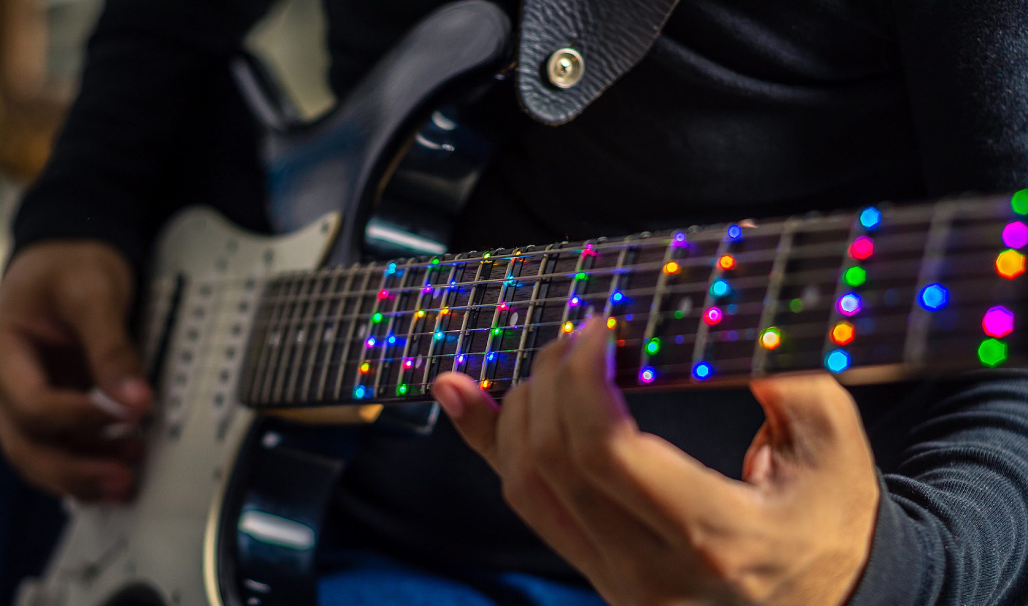
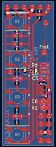
This week I primarily worked on the assembly of the fretboard PCBs and the mechanical modifications to the guitar. The fretboard PCBs arrived on Monday and I began assembly on Wednesday. Roboclub’s solder paste went bad so I began this process by hand soldering the boards. 7 of the smaller PCBs were done by hand. While not the most time-efficient, this was a valuable lesson in using tools such as SMD soldering tweezers and soldering small SOT-23-5 components without bridging pins. On Friday, I brought the boards and parts to the TechSpark PCB Fabrication Lab, where I did the assembly of the rest of the boards. This was done using the solder paste and reflow oven available in the Fab-Lab. After soldering the boards, I used the microscope to perform some touch-up work on some of the boards. In total, 8 of the smaller PCBs and 9 of the larger PCBs were assembled. These boards are shown below.

To validate the functionality of the boards, I created a perf-board with pins that would rest on the exposed pads of the board and run a series of automated tests on the board using an RPi Pico. However, I found that without pogo pins it was almost impossible to make contact with all the pads simultaneously, making testing impossible. I was able to test the functionality of the LEDs on all the boards using this system, but the D-flip flops could not be tested. I may be able to angle the header pins on the perf-board in such a way that they make better contact with the board. Getting this tool to function will allow us to be confident in the functionality of the boards before soldering them and mounting them to the fretboard.
The other main task that I have been working on this week is the mechanical modification of the guitar. The first task related to this was connecting wires to each string of the guitar so we can read the electrical stimulus on each string. A wire was connected to the termination point of each string via a solder joint and run into the body of the guitar through holes driller directly under the ends of the strings. This minimizes the amount of visible wiring needed on the guitar, which is one of our goals with the modifications. The image below shows the wires connected to each string before they are run into the guitar.

The wires terminate in bullet connectors, which will allow us to quickly connect and disconnect them from the main Pi Hat board when we need to remove it.
Progress has also been going well with the parts for mounting the Pi. I have 3D printed a new case for the Pi that will hold both it and the Pi Hat securely. I also 3D printed a new panel to cover the hole in the side of the guitar where the amp previously was, since the one I previously made did not fit very well.’
The main mechanical task, the carving of the fretboard channels, has not been going well. I attempted to cut one channel by hand, but this proved to be far too time-consuming. Roboclub’s mill was broken this weekend and the person working on repairing it was gone for the weekend, so I was unable to make progress with machining it. However, this week I hope to be able to get mill training and assistance in mounting the guitar to the mill. The backup plan would be to use a dremel, but the dremel is not ideal since it cannot be oriented in the desired way, meaning the channels would have a U shape, not rectangular. This could be filed down if desired, but would be very time-consuming.
In terms of schedule, I would have liked the channels to have been cut this weekend. Having the channels would have assisted in cutting wires to length between the fretboard PCBs, but I think that I can proceed with this without the channels. Tushaar is currently able to use the trainer fretboard to test his code, but I would like to switch over to testing on the actual guitar very soon. Tomorrow I will attempt to mount the Pi in the guitar and will test dremel-ing on the practice fretboard.
My main deliverables for this week will be the channels carved into the guitar and the PCBs soldered together and connected to the Pi.
Abet Question:
To verify that our system will meet the design and use case requirements we will be running numerous tests on our design.
For the hardware side of the project, these consist of:
- Measuring current through the user
- Verifying functionality of each LED and finger placement sensor
- Determining the accuracy of strum detection
- Determining latency from strum to Teensy updating state
- Evaluating the comfort of the system
The verification of the fretboard PCB LEDs has been completed. This was done using an RPi Pico to cycle each NeoPixel through RGB values, allowing me to verify that each LED was functioning. I have also verified that we can source enough current to drive all of the LEDs at half brightness. This was discussed in my status report last week, in which I performed thermal testing of the power distribution on the Pi Hat. I found that while pulling 5A from the power supply, which is the maximum expected load, the voltage drop on the 5V line was acceptable and the traces did not overheat.
Very soon I will be measuring the current passed through the user when contacting a fret being driven high. We have tested this in the past with a multimeter that went down 0.1mA, but we will be collecting current measurements using a lab bench meter for additional accuracy. I will measure both the current passed through the skin under “normal” conditions for a handful of people as well as the short circuit current, which is indicative of the absolute highest current that could flow through the user, assuming they had 0 resistance. We have stringent requirements for these values, so it will be easy to determine if our device is meeting our requirements.
I have also verified the functionality of the strum detection using a series of 1/8th note strums at 100BPM and did not observe any missed or extraneous strums. This will be re-checked once the system is integrated onto the guitar. We will perform a series of 1/8 note strums at 100BPM on each string and count the number detected by the system, which will let us determine the system’s accuracy. We will then compare this result to our system requirements to evaluate the system.
Latency testing for strum-to-LED delay will be done by probing a string and the LED data line simultaneously with an oscilloscope. We will trigger on a rising edge on the voltage of the string, indicating the user is strumming, and will measure the time delay until the data line for the LEDs goes quiet. Our main Teensy loop is currently operating at well over 100Hz, including driving the LEDs and reading strums, so we expect no issues hitting out latency requirements.


