This week, I worked on a wide variety of tasks. These tasks included:
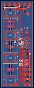
- A board/program to test the assembled PCBs
- Redesigning 3D printed covers for the fretboard PCBs
- Carving out the channels in the guitar fretboard
- Connecting the fretboard PCBs together
- Connecting the Pi Hat PCB to the guitar strings, pick, and fretboard PCBs
- Testing the hardware with Tushaar
- Designing a 3D printed cover to protect the wires on the bottom of the guitar
Starting with the testing of the PCBs, this was done since the new PCBs featured the fix required for the D-flip-flops.

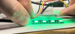
Shown above is a perfboard with header pins mounted to it. In the absence of proper pogo pins, I angled the headers at around 45 degrees to allow the pins to firmly contact the fretboard PCB. A Raspberry Pi Pico ran a series of tests on the D-flip-flops, providing a series of clock and data inputs and reading the output. The results of the tests were then displayed on the fretboard LEDs, which doubled as a verification of the LED functionality. Not including the time required to assemble the tester, this allowed for all of the boards to be tested in only around 5 minutes. The tester did properly find one soldering issue on a board, likely saving quite a bit of time worth of debugging if we had proceeded without testing.

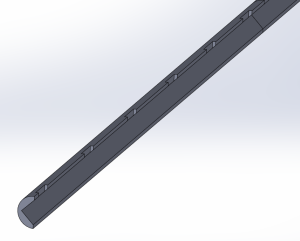
While preparing to mount the boards, I also designed a cover for the PCBs. Our previous plan was to conformal coat the boards, but that would mean the user is still pressing onto an uneven surface. With a cover for the PCB, this prevents the user from touching the electronics and gives them a flat surface to press on. The design for the covers is shown above
Once the boards were assembled and ready, I began carving out the channels in the guitar. This was ultimately done with files and a dremel and was quite time-consuming. Tushaar was able to help out and do around 6-7 of the channels while I began soldering the fretboard PCBs together. There were a handful of mishaps while performing the carving. These included knocking off the guitar nut (the part that guides the strings at the top of the guitar) and breaking off a fret. Both of these were able to be fixed with very little evidence of repair.

To connect the PCBs together, I used 30 AWG wire-wrap wire and 26 AWG silicone wire. The D-flip-flop connections were done with thee 30 AWG wire due to the low current required. While not entirely necessary, the 4 wires between each fret were bundled together with heatshrink. These connections are shown above. The LED connections were done with 26 AWG wire due the higher current required.
To connect the Pi to the strings, pick, and fretboard PCBs, I used numerous banana plugs. Banana plugs were likely not the best choice of connector since they need to be done individually, but I did not have any JST connectors on hand. These banana connectors enable the rapid connection of the Pi/Pi-Hat to the rest of the guitar and enable it to be removed for repairs if needed. Holes were drilled in strategic locations around the guitar to route wires through, allowing for external wiring to be minimized.
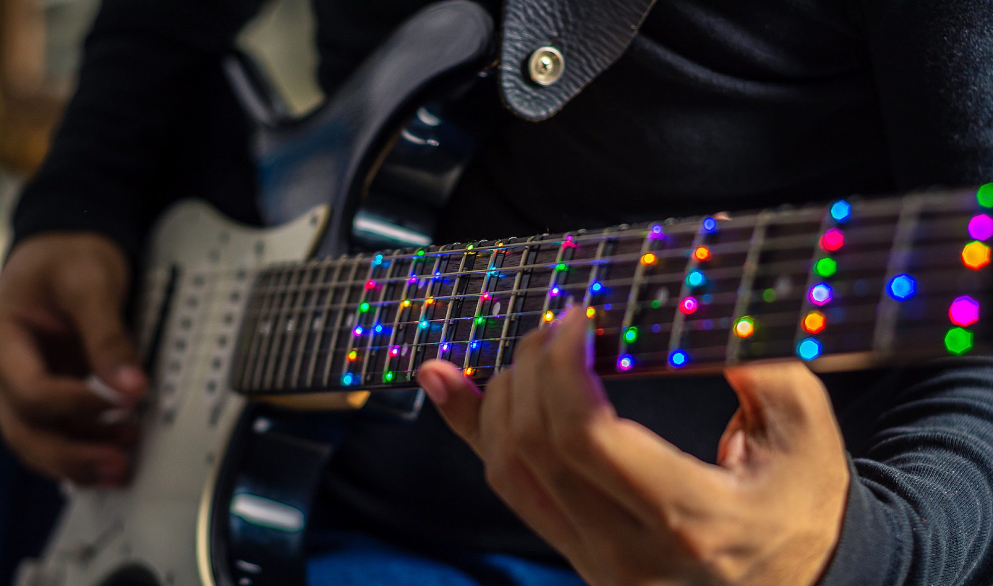
Once the guitar was assembled, Tushaar and I used Ashwin’s webapp to upload songs to the Teensy and verify the functionality of all the LEDs and the finger placement sensors. We tested a variety of MIDI files and were able to get the firmware to a point where the training mode is almost complete from a hardware and firmware perspective.
One issue we did have was with the wires along the bottom of the guitar being sensitive to being moved, which is not ideal considering the user will be moving their hands up and down the guitar fretboard. We had this disconnect one of the 30 AWG wire connections and break the fret sensors. To resolve this, I designed a 3D printed device to cover the wires and protect them, with the added benefit of making the guitar more comfortable. The CAD model for this is shown below

This was then attached to the guitar, as shown below

So far this has proven quite effective at protecting the wires on the guitar and cleaning up the overall look of the guitar.
I am currently on schedule and my main tasks for next week will be performing the required hardware testing and verification and installing the PCB covers. We have held off on the covers while verifying functionality since placing the covers on will make repairs significantly more difficult.
My main deliverables for next week will be results for some of the hardware testing and the guitar fret covers installed. I also may work on some stretch goals, including adding the option to battery power the device. As discussed previously, for safety reasons we have no intention of implementing a charging circuit for an internal battery. Charging is when lithium batteries are most likely to combust, so removing charging from the equation makes battery power much safer. This would mainly be a quality-of-life feature for demoing, as it would remove the need to be tethered to an outlet. When testing though, Tushaar and I did not have any problems with the wall adapter, so this remains a perfectly viable solution for powering the device.


