Owen’s Status Report for 12/9/2023

This week I mainly worked on setting up the firmware to take in a metronome volume in the MIDI file. This involved modifying Tushaar’s MIDI file parsing code to take in an additional parameter at the beginning of the file. I then transformed the 0-10 volume provided by the Pi into a PWM value to provide to the buzzer and then passed this into the metronome functions I wrote last week.

I also worked on downloading various MIDI files and uploading them to the system. This was done to verify that the system can properly handle numerous different MIDI files. This also allowed us to build up a library of songs for people to play during the demo.

While Ashwin was working on the statistics collection, I play tested the various songs and generated data for him to display. This also allowed us to verify that the firmware fix Tushaar implemented earlier in the week was functional. The issue was that after around 40 minutes various system values would overflow, since ~36 minutes corresponds to approximately 2^31 us. We experienced no issues with the system.

Additionally, I worked on making the ‘in waiting’ LED pattern on the guitar slightly more dynamic.

In order to more easily show off the Pi-Hat and Teensy electronics, I finished soldering our backup Pi-Hat board and assembled it with my personal RPI 4B and Teensy 4.1. This will prevent us from needing to take the electronics out of the guitar during the demo.

My final main tasks for this week were working on the poster, which consisted of taking photos of the assembled system and taking the electronics out of the system for imaging.

Progress is on schedule and future work only consists of final preparations for the demo and working on the final video and report.

Owen’s Status Report for 12/2/2023

This week, I worked on a handful of tasks. These included:

  • Testing various system latencies and metrics
  • Finishing up some mechanical work on the guitar
  • Working on fixing the Pi’s reading of the Teensy’s UART data
  • Implementing the buzzer on the Teensy
  • Helped with determining the tempo of songs in the Pi software

System Testing:

The first thing tested was the functionality of all fretboard finger placement sensors and LEDs. I did this by using Tushaar’s functions and writing some firmware to light up the LED under where the user is pressing. With this in place, I tested each of the 56 possible finger placements 5 times each, and the corresponding LED lit up each time the sensor was tested. This has also been continuously tested as we have been testing various songs on the guitar during integration testing. This means that the control of the LEDs and the reading of the finger placement is 100% accurate.

The next requirement I tested was the current that can pass through the user. Our requirements state that this must be below 1mA, which is why we implemented a 3.3kOhm series resistor. This value was verified with a 0.1mA accurate multimeter before continuing with system construction and testing, but this week I performed formal testing with lab-bench equipment capable of 0.01uA accuracy. The average short circuit (assuming the user is a 0 Ohm short) was 5.37uA. This dropped to approximately 0.80uA when put through various individuals. This is over 1000-fold below our target average current, so this test was a success. Average current is so low because the fret sensors are only sampled for a handful of microseconds, and the full firmware loop is on the order of milliseconds. Using a series shunt resistor and an oscilloscope I measured the peak short circuit current to be 0.762mA, which lasts for 10us. This is ensured to be below 1mA by the series 3.3kOhm resistor and by a ~0.5V voltage drop on a diode.

By modifying Tushaar’s firmware with code to time the main loop, I was able to find that the system’s main loop time was 1555+-10us for both system modes. The similarity is because by almost all of the loop time is spent reading from the fretboard sensors and writing to the LEDs, which both modes do identically. This loop time directly corresponds to an LED refresh rate of 1555us, or 640Hz. This exceeds our requirement of 50Hz.

Strum to LED update delay was determined using an oscilloscope. I set the oscilloscope to trigger on a strum. This was done by probing the string the pick struck (while the pick was at ~3.3V minus a diode drop) and triggering on a falling edge, meaning the pick has left the string. I then probed the LED data line and determined that there is a 1850us delay between the strum and when the final LED on the fretboard receives its data. One interesting finding is that this is longer than the system loop time. I did observe that the system loop actually alternated between 1ms and 2ms, so I believe that 1. The NeoPixel library does not block on the functions used to write to the LEDs and 2. the library occasionally slows down the loop to 2ms to clear its output buffer. Nevertheless, the LEDs update far more frequently than our requirements, to the point where we are at the absolute limit of how frequently a strip of 60 NeoPixels can update.

Current consumption was measured for each component. The results were:
Pi: 0.45A
Teensy + Fretboard flip flops: 0.12A
LED current at 1/2 brightness rainbow*: 0.39A

The Pi draws far less current than expected, so we could run the LEDs at max brightness, but from our testing, this is too bright anyways.
*We color code each string, so this test was performed by lighting up each LED to its corresponding color

Strum rate was tested by strumming each string 200 times to the beat of a metronome and using the Teensy to count strums. I was able to strum up to 300BPM before strums began to be dropped (requirement was 200)

Buzzer audio level was 75 dB at the average user position

System battery life was ~3.5 hours, but this can be extended to around 4 hours. I take very good care of my LiPo batteries though and 3.5 hours corresponded to as discharged as I was willing to go for a test.

Metronome:
The main other task I worked on was implementing the buzzer firmware to alleviate some work from Tushaar. This involved doing some things with arduino that I was relatively unfamiliar with, such as working with structs, creating .h files, etc. I ultimately was able to create an easy to use function that takes in a BPM, which I had Tushaar provide via the data received over UART. I also worked on reading in the BPM from the MIDI file on the software, although we ultimately ended up going with Ashwin’s approach since my function failed on a select handful of MIDI files.

I am currently on schedule and have no hardware tasks remaining besides testing strum to webapp latency, which our current estimates put right around 250ms.

For next week I will be mainly working on the final poster, prepping materials for the demo, and working on the final report. I will also continue to offer firmware/software debugging help as needed

Owen’s Status Update for 11/18/2023

This week, I worked on a wide variety of tasks. These tasks included:

  • A board/program to test the assembled PCBs
  • Redesigning 3D printed covers for the fretboard PCBs
  • Carving out the channels in the guitar fretboard
  • Connecting the fretboard PCBs together
  • Connecting the Pi Hat PCB to the guitar strings, pick, and fretboard PCBs
  • Testing the hardware with Tushaar
  • Designing a 3D printed cover to protect the wires on the bottom of the guitar


Starting with the testing of the PCBs, this was done since the new PCBs featured the fix required for the D-flip-flops.

Shown above is a perfboard with header pins mounted to it. In the absence of proper pogo pins, I angled the headers at around 45 degrees to allow the pins to firmly contact the fretboard PCB. A Raspberry Pi Pico ran a series of tests on the D-flip-flops, providing a series of clock and data inputs and reading the output. The results of the tests were then displayed on the fretboard LEDs, which doubled as a verification of the LED functionality. Not including the time required to assemble the tester, this allowed for all of the boards to be tested in only around 5 minutes. The tester did properly find one soldering issue on a board, likely saving quite a bit of time worth of debugging if we had proceeded without testing.


While preparing to mount the boards, I also designed a cover for the PCBs. Our previous plan was to conformal coat the boards, but that would mean the user is still pressing onto an uneven surface. With a cover for the PCB, this prevents the user from touching the electronics and gives them a flat surface to press on. The design for the covers is shown above

Once the boards were assembled and ready, I began carving out the channels in the guitar. This was ultimately done with files and a dremel and was quite time-consuming. Tushaar was able to help out and do around 6-7 of the channels while I began soldering the fretboard PCBs together. There were a handful of mishaps while performing the carving. These included knocking off the guitar nut (the part that guides the strings at the top of the guitar) and breaking off a fret. Both of these were able to be fixed with very little evidence of repair.


To connect the PCBs together, I used 30 AWG wire-wrap wire and 26 AWG silicone wire. The D-flip-flop connections were done with thee 30 AWG wire due to the low current required. While not entirely necessary, the 4 wires between each fret were bundled together with heatshrink. These connections are shown above. The LED connections were done with 26 AWG wire due the higher current required.

To connect the Pi to the strings, pick, and fretboard PCBs, I used numerous banana plugs. Banana plugs were likely not the best choice of connector since they need to be done individually, but I did not have any JST connectors on hand. These banana connectors enable the rapid connection of the Pi/Pi-Hat to the rest of the guitar and enable it to be removed for repairs if needed. Holes were drilled in strategic locations around the guitar to route wires through, allowing for external wiring to be minimized.

Once the guitar was assembled, Tushaar and I used Ashwin’s webapp to upload songs to the Teensy and verify the functionality of all the LEDs and the finger placement sensors. We tested a variety of MIDI files and were able to get the firmware to a point where the training mode is almost complete from a hardware and firmware perspective.

One issue we did have was with the wires along the bottom of the guitar being sensitive to being moved, which is not ideal considering the user will be moving their hands up and down the guitar fretboard. We had this disconnect one of the 30 AWG wire connections and break the fret sensors. To resolve this, I designed a 3D printed device to cover the wires and protect them, with the added benefit of making the guitar more comfortable. The CAD model for this is shown below

This was then attached to the guitar, as shown below

So far this has proven quite effective at protecting the wires on the guitar and cleaning up the overall look of the guitar.

I am currently on schedule and my main tasks for next week will be performing the required hardware testing and verification and installing the PCB covers. We have held off on the covers while verifying functionality since placing the covers on will make repairs significantly more difficult.

My main deliverables for next week will be results for some of the hardware testing and the guitar fret covers installed. I also may work on some stretch goals, including adding the option to battery power the device. As discussed previously, for safety reasons we have no intention of implementing a charging circuit for an internal battery. Charging is when lithium batteries are most likely to combust, so removing charging from the equation makes battery power much safer. This would mainly be a quality-of-life feature for demoing, as it would remove the need to be tethered to an outlet. When testing though, Tushaar and I did not have any problems with the wall adapter, so this remains a perfectly viable solution for powering the device.


Owen’s Status Report for 11/11/2023

This week I primarily worked on the assembly of the fretboard PCBs and the mechanical modifications to the guitar. The fretboard PCBs arrived on Monday and I began assembly on Wednesday. Roboclub’s solder paste went bad so I began this process by hand soldering the boards. 7 of the smaller PCBs were done by hand. While not the most time-efficient, this was a valuable lesson in using tools such as SMD soldering tweezers and soldering small SOT-23-5 components without bridging pins. On Friday, I brought the boards and parts to the TechSpark PCB Fabrication Lab, where I did the assembly of the rest of the boards. This was done using the solder paste and reflow oven available in the Fab-Lab. After soldering the boards, I used the microscope to perform some touch-up work on some of the boards. In total, 8 of the smaller PCBs and 9 of the larger PCBs were assembled. These boards are shown below.

To validate the functionality of the boards, I created a perf-board with pins that would rest on the exposed pads of the board and run a series of automated tests on the board using an RPi Pico. However, I found that without pogo pins it was almost impossible to make contact with all the pads simultaneously, making testing impossible. I was able to test the functionality of the LEDs on all the boards using this system, but the D-flip flops could not be tested. I may be able to angle the header pins on the perf-board in such a way that they make better contact with the board. Getting this tool to function will allow us to be confident in the functionality of the boards before soldering them and mounting them to the fretboard.


The other main task that I have been working on this week is the mechanical modification of the guitar. The first task related to this was connecting wires to each string of the guitar so we can read the electrical stimulus on each string. A wire was connected to the termination point of each string via a solder joint and run into the body of the guitar through holes driller directly under the ends of the strings. This minimizes the amount of visible wiring needed on the guitar, which is one of our goals with the modifications. The image below shows the wires connected to each string before they are run into the guitar.

The wires terminate in bullet connectors, which will allow us to quickly connect and disconnect them from the main Pi Hat board when we need to remove it.

Progress has also been going well with the parts for mounting the Pi. I have 3D printed a new case for the Pi that will hold both it and the Pi Hat securely. I also 3D printed a new panel to cover the hole in the side of the guitar where the amp previously was, since the one I previously made did not fit very well.’

The main mechanical task, the carving of the fretboard channels, has not been going well. I attempted to cut one channel by hand, but this proved to be far too time-consuming. Roboclub’s mill was broken this weekend and the person working on repairing it was gone for the weekend, so I was unable to make progress with machining it. However, this week I hope to be able to get mill training and assistance in mounting the guitar to the mill. The backup plan would be to use a dremel, but the dremel is not ideal since it cannot be oriented in the desired way, meaning the channels would have a U shape, not rectangular. This could be filed down if desired, but would be very time-consuming.

In terms of schedule, I would have liked the channels to have been cut this weekend. Having the channels would have assisted in cutting wires to length between the fretboard PCBs, but I think that I can proceed with this without the channels. Tushaar is currently able to use the trainer fretboard to test his code, but I would like to switch over to testing on the actual guitar very soon. Tomorrow I will attempt to mount the Pi in the guitar and will test dremel-ing on the practice fretboard.

My main deliverables for this week will be the channels carved into the guitar and the PCBs soldered together and connected to the Pi.


Abet Question:

To verify that our system will meet the design and use case requirements we will be running numerous tests on our design.

For the hardware side of the project, these consist of:

  • Measuring current through the user
  • Verifying functionality of each LED and finger placement sensor
  • Determining the accuracy of strum detection
  • Determining latency from strum to Teensy updating state
  • Evaluating the comfort of the system

The verification of the fretboard PCB LEDs has been completed. This was done using an RPi Pico to cycle each NeoPixel through RGB values, allowing me to verify that each LED was functioning. I have also verified that we can source enough current to drive all of the LEDs at half brightness. This was discussed in my status report last week, in which I performed thermal testing of the power distribution on the Pi Hat. I found that while pulling 5A from the power supply, which is the maximum expected load, the voltage drop on the 5V line was acceptable and the traces did not overheat.

Very soon I will be measuring the current passed through the user when contacting a fret being driven high. We have tested this in the past with a multimeter that went down 0.1mA, but we will be collecting current measurements using a lab bench meter for additional accuracy. I will measure both the current passed through the skin under “normal” conditions for a handful of people as well as the short circuit current, which is indicative of the absolute highest current that could flow through the user, assuming they had 0 resistance. We have stringent requirements for these values, so it will be easy to determine if our device is meeting our requirements.

I have also verified the functionality of the strum detection using a series of 1/8th note strums at 100BPM and did not observe any missed or extraneous strums. This will be re-checked once the system is integrated onto the guitar. We will perform a series of 1/8 note strums at 100BPM on each string and count the number detected by the system, which will let us determine the system’s accuracy. We will then compare this result to our system requirements to evaluate the system.

Latency testing for strum-to-LED delay will be done by probing a string and the LED data line simultaneously with an oscilloscope. We will trigger on a rising edge on the voltage of the string, indicating the user is strumming, and will measure the time delay until the data line for the LEDs goes quiet. Our main Teensy loop is currently operating at well over 100Hz, including driving the LEDs and reading strums, so we expect no issues hitting out latency requirements.


Owen’s Status Report for 11/4/23

The main task I worked on at the beginning of this week was debugging the issue with the fretboard PCB flip flops. On Saturday night, I discovered that the filtering of the data lines seemed to resolve the issue, and on Sunday I soldered together 5 boards with the fix to test them. After using an oscilloscope to confirm the fix, I quickly updated the fretboard PCBs so they were ready to submit on Monday. The changes made were the addition of an RC filter on the data input to each flip flop. The issue this resolves is that without the filters, on a single clock edge an input signal could pass through one flip-flop and end up on the output of the next flip flop. Although according to the data sheet we should not have needed this RC circuit to satisfy hold time, the circuit appears to function now. The clock is also filtered, although the time constant for this filter is much lower and only serves the purpose of reducing ringing. This is done on the main PiHat PCB before distribution to the fretboard PCBs. The updated PCB schematic and layout are shown below.

This updated board was created in two sizes in order to better accommodate the changing spacing between the strings along the length of the guitar. The order was placed on Monday and should arrive in the middle of next week.

In order to test the functionality of my fretboard PCB fix, I wired the PCBs to  my personal guitar temporarily and verified that the system could detect where I was placing my finger on the fretboard accurately. After verifying the PCBs worked, I passed the hardware and code off to Tushaar so he could integrate it into his firmware

Both the PiHat PCBs and DigiKey order arrived on Wednesday. On Wednesday night I assembled a PiHat PCB and began preliminary testing of the system. A completed board is shown below:

So far the following tests have been performed:
1. Voltage drop of power supply and PCB traces for the Pi and LEDs. The voltage at the Pi input was 4.9V at maximum current, which is above the Pi’s 4.75V minimum

2. Measuring thermals of the board when pulling the maximum expected current. Performed nominally

3. Testing the 3.3V to 5V logic level shifter for the NeoPixels. Performed nominally

4. Verifying the functionality of the buzzer. Performed nominally

5. Verifying powering the Teensy via USB does not attempt to power the Pi or LEDs, and that the Teensy can be connected via USB safely while also powering the system via a barrel jack. Performed nominally

A thermal image of the board while pulling 5A (the expected maximum is only 3A) through the Pi’s power traces:

As can be seen in this image, the maximum temperature reached by the trace is only 38C, which is completely reasonable for almost double the expected maximum current.

The final thing that I have been working on is planning the modification of the guitar and mounting of the electronics. I have begun creating CAD models and prints to support the PCBs, such as covers for the fretboard PCBs and a mount for the Pi and Pi Hat, which are shown below

Caption: A cover for the fretboard PCB that prevents the user from touching any exposed metal contacts

Caption: A preliminary case for the Pi and Pi Hat.

Our current plan is to insert the Pi and Pi Hat into the region of the guitar currently occupied by the built-in amp. I have managed to remove the amp and its internal connections in the guitar. We will be able to make a Pi case that directly mounts into this slot just like the original amplifier, allowing us to easily have access to the Pi for repairs and/or testing. We then plan to drill small holes in the side of the guitar to run wires with connectors on them to the fretboard and the end of the guitar strings

Caption: The hole in the guitar that the electronics will be inserted into


My progress is currently on schedule. The deadline Tushaar and I set for fixing the fretboard PCBs or moving to our alternative approach enabled us to stay on schedule and be confident we would not fall behind schedule. The fretboard PCBs should be in by the middle of next week, which will give me a bit of time to assemble them and install them. The main tasks I currently have left besides this will be the mechanical modification of the guitar.

This week I plan to begin carving out the channels for the fretboard PCBs and finalizing the mounts for the Pi-Hat PCB inside the guitar. I have been consulting with some of the shop-masters in Roboclub regarding the best way of accomplishing this task safely and efficiently. I will also be working on the assembly and testing of the fretboard PCBs when they arrive this week


Owen’s Status Report for 10/28/23

This week I primarily worked on the testing of the fret-detection using the fretboard PCBs. This has not gone smoothly and has taken up most of my time for the week. Besides this, the Pi-Hat PCB was tweaked slightly and ordered, along with the required parts from DigiKey.

While I did test the functionality of the fretboard PCBs shortly after assembling them, when Tushaar and I went to test the system with some basic string-fret switches that we made, we ran into some problems. The primary issue was that the output on the D-flip-flop seemed to be going high on some of the flip flops further down the shift register earlier than expected. Tushaar and I first noticed this on Tuesday night and spent from around 7pm to 11pm working on this. The main realizations made was the one stated previously, as well as determining that this issue occurred no matter what the clock speed. We also looked through the timing information on the flip-flop datasheet and ensured that we were not violating any parameters such as hold or setup time.

Before class on Wednesday, I hand soldered some extra D-flip flops to PCBs and tested them, and determined that they were working. Thus, for our Wednesday meeting, Tushaar and I focused on determining what the differences were in the two systems. We came up with the following:
1. The hand soldered boards did not have LEDs on them

2. The hand soldered boards used shorter wires connecting them together

3. The hand soldered boards did not have the current limiting resistor and accompanying diode on their output

4. The hand soldered boards were not put on a hot plate

Of these, we highly doubted 1 or 3 to be the cause. Our primary theory was that the flip-flops were damaged by the hot plate, so I removed the flip-flops from the non-working PCBs and hand soldered new flip-flops. This did not resolve the issue. Further testing of the original set of working hand soldered boards revealed that under certain conditions, I could cause outputs to appear one clock cycle earlier than expected. This was done by adding capacitance to the clock line, which I believe resulted in the output signal from the previous flip-flop arriving slightly before the clock edge instead of simultaneously. This resulted in the second flip-flop storing the value that was going into the first flip-flop’s input on the clock edge. I added a resistor and capacitor delay circuit to the data line and it appears to have solved the issue, although I have yet to do this to the fully soldered set of PCBs to confirm this works on them as well.

Tushaar and I have discussed contingency plans and have set a cut-off time for switching over to the contingency plan. The plan is to run 14 individual lines, one to each fret. We believe that by doing this with magnet wire, it would not be intrusive to the user at all. This approach requires numerous free GPIO pins on the Teensy. Almost as soon as the issue arose, I began working on revising the PCB to break out a handful more Teensy GPIO pins to ensure that we had enough for this plan. The board ordered on Thursday has these additional pins in place.

This weekend I plan to add the RC delay circuit in between each fretboard PCB to test this solution, and if it works, I will revise the PCBs and order them. If the solution does not work, I will also modify the PCBs accordingly and order them, as we have not found any issues with the LEDs on them.

One other thing that I worked on was a system to detect which string is strummed. This was done using a pick with an electrode on it and connecting the pick to the microcontroller via a flexible wire. This turned out to be extremely accurate for both detecting which string is strummed and when, making the strum detection circuit somewhat obsolete. I have found that especially as am amateur guitar player, I can accidentally create noises when moving my fingers that could trigger the strum detection circuitry. However, using the pick seems to be much more resilient to ignoring these extraneous noises, making it a more reliable solution.


Due to the fretboard PCB issues, we are behind schedule on them. We will be ordering them this week. Assembly will likely be faster than originally expected which alleviates some concern, but we may choose to use some of our budget to try and expedite the order. While waiting for the Pi Hat PCBs and fretboard PCBs, I will begin the mechanical modifications of the guitar, mainly planning the mounting of the Pi and determining the best method in which to carve channels for the fretboard PCBs. I believe that this will put me on schedule to mount the Pi and fretboard PCBs in a timely manner once they are received.

As mentioned previously, the main deliverables for this week will be ordering the fretboard PCBs and a full plan for the mechanical mounting of the PCBs and Pi, as well as some progress on this task.

Owen’s Status Report for 10/21/23

As you’ve now established a set of sub-systems necessary to implement your project, what new tools are you looking into learning so you are able to accomplish your planned tasks?

To accomplish the hardware tasks planned for this project, I have had to learn how to use various software tools, along with a handful of physical tools.

The main software tool that I have been learning to design the PCBs for the project has been KiCAD. In the past, I have worked with Altium and EasyEDA but I wanted to branch out and learn more tools. EasyEDA served me well for a handful of designs but I wanted slightly more professional software, and one with a larger community. Although I also have experience with Altium, I personally do not enjoy it for personal projects, and I wanted to familiarize myself with the workflow associated with software other than Altium.  Learning KiCAD primarily consisted of familiarizing myself with the location of various options and menus, such as customizing the DRC rules to match those of JLCPCB. I also had the opportunity to learn how to import symbols from Digikey and create/import footprints for parts. In the past I have either been able to find parts in the built-in catalog or in my company’s parts library, so it was good to learn the process of creating my own parts. I also had to learn how to create a precise board outline and mounting holes, which I have not had experience with in the past. In previous projects, I have just created a board and then created a mount to fit it in CAD, but for this project, my boards must mount onto existing hardware such as a Raspberry Pi. I have also been learning new skills in Arduino to test my hardware. For example, I have learned how to use the NeoPixel library to run the LEDs on the PCBs as well as learned how to detect interrupts with the Teensy and operate the D-flip-flops on the PCBs in order to accelerate my testing.

In terms of physical tools, I have been learning to work with PCB stencils and surface mount soldering. I have dealt with some surface mount soldering of 0402-0805 resistors and capacitors, but not in large quantities or anything more complex. Additionally, in the past I have always hand-soldered these parts. However, since we need around 14-15 of the fretboard PCBs, I am learning how to use PCB stencils, solder paste, and hot plates in order to expedite the soldering process. I have also been learning about a variety of sensors in our quest to find solutions to some of our sensing problems. This consists of learning how capacitive touch sensors work, as well as how the inductive and piezoelectric pickups used in many guitars function.

For the future, I am mainly interested in learning how MIDI files work a bit more so that I am more familiar with the work being done by software and firmware and can better integrate the hardware with these systems.

Weekly Update

This week I primarily worked on the assembly and testing of the fretboard PCBs and the design of the Pi-Hat.

The assembly of the fretboard PCBs went well. This was done using the SMD stencil and a hot plate. In total 5 were assembled for Tushaar to use for testing. The pad for the current limiting resistor was replaced with a surface mount diode. The resistor will be added between the fret pad and the fret, so the safety of the system is not compromised by this. The functionality of the LEDs was tested, along with the D-flip-flops used for driving each fret high.

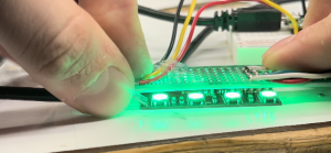
Top: One of the fretboard PCBs on a hot plate
Bottom: Initial tests of the LEDs on the fretboard PCB

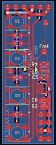
There are a couple of changes that need to be made to the PCB, most of which were implemented this week. The first change is adding a pad for the SMD diode in series with the current limiting resistor. The next change was to switch out the through-hole pads with pads on just the surface of the PCB. If solder flows though the through-hole pad it can result in an uneven bottom of the board, making mounting it more difficult. The next change was to make the PCB narrower by around 1.5mm. The initial measurements of the PCB were taken from a photo, and as a result, the PCB is slightly too wide to fit next to the 14th fret. The final change that needs to be made is to adjust the spacing of the LEDs. Currently, the spacing is reasonable for the middle of the guitar, but by making a few variants of the board, we can better match the spacing of the strings. The updated board layout is shown below

D1-D4 on the left are the LEDs. The top pads are the connections for the LEDs, and the bottom right ones are for the fret-driving flip-flop, which is on the right side of the board.

This week I also worked on the Pi-Hat PCB. The main change to the plan for the PCB is to offload the strum detection to a perfboard. The circuit needs a lot of tuning and this can be better done on a perfboard. This reduces the risk of the strum detection not functioning.
The PCB consists of the following components:

  1. A 5V barrel jack connector with filter capacitors. The 5V directly powers the Pi and LEDs and the Teensy is powered through a Schottky diode. This prevents backpowering the micro USB port on the Teensy, allowing the Teensy to be plugged into a computer while the system is also powered. It also prevents the USB port from attempting to drive the LEDs, which would draw too much current.
  2. The Teensy 4.1. A handful of the I/Os are sent directly to pads for future needs. 4 pads have external pull-down resistors and will be connected to the strings of the guitar. 10 of the I/O are routed directly to Pi GPIO pins allowing for communication. There are currently no plans to use all 10 of these, but this enables expansion in the future.
  3. A header to mate directly to the header on the Pi. In addition to the GPIOs routed to the Teensy, 4 I/O pins are broken out to pads for future use
  4. An active buzzer driven off a Teensy PWM pin. We can PWM the power to the buzzer to control the volume of the buzzer. A resistor pad is also included for current limiting the buzzer, although the current plan is to place a jumper on this pad.
  5. A 3.3V to 5V logic level converter to convert the 3.3V signal from the Teensy to a 5V signal for the LEDs. This may or may not be needed according to testing, but according to the LED datasheet the signal should be at least 3.6v

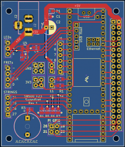
The current layout of the board is shown above. The Pi header is on the right side and the Teensy is the component to the left of the headers. The top left is the power barrel jack. Along the left side is I/O and at the bottom of the board is the buzzer.

For the most part my progress is on track. The fretboard PCBs still need their LED spacing revised, but this can be done fairly quickly once the desired spacing is determined. The Pi-Hat PCB design is ahead of schedule. These boards will likely be ready to be sent out in the same order, reducing the shipping costs incurred. The PCB assembly turned out to be faster than I expected, so this will not take as long as indicated on the schedule.

The DigiKey cart has also been compiled for the PCB orders, so that can be sent out this week.

The final thing that I worked on was the strum detection circuitry. It is mostly working on a breadboard so I hope to perform some final testing of that before soldering it up.

My main deliverables for next week will be ordering the PCBs and sending out the DigiKey order. I also hope to solder the strum detection circuit on perfboard.

Owen’s Status Report for 10/7/23

What did you personally accomplish this week on the project? Give files orphotos that demonstrate your progress. Prove to the reader that you put sufficienteffort into the project over the course of the week (12+ hours). Is your progress on schedule or behind? If you are behind, what actions will betaken to catch up to the project schedule? What deliverables do you hope to complete in the next week?

This week I primarily worked on the initial design of the main PCB for the guitar that will connect the Teensy, Pi, and the the various sensors/outputs. The current plan for the PCB is to provide power via a 5V barrel jack. This will be split and sent to the Pi, Teensy, and LEDs. 3.3V will be supplied by the Teensy’s onboard linear regulator, and the ~200mA limit is more than enough for our 3.3V needs. The Pi to Teensy communication will be done simply through a handful of traces connecting pins on the Teensy to Pi GPIO pins. These will be used for both UART communication and for interrupts sent from the Pi.  The current plan is for 1 UART channel and around 10 general-purpose lines running between the Teensy and the Pi. This should be sufficient for the number of interrupts we are currently planning for, and allows for expansion in the future or the addition of some other form of communication between the Pi and Teensy. Both the Teensy and Pi will have a handful of their GPIOs brought to solderable pads to enable additional sensors to connect in the future. These will be accompanied by sets of GND and 3.3/5V pads on the board to power external sensors/devices.

The main other components on the board will be a 3.3V-5V level shifter for the LEDs, an active buzzer to serve as an easy-to-control metronome, and the strum detection circuitry. Since the guitar shipping from Amazon took longer than expected, the fine-tuning and testing of the circuit has been delayed a bit. Due to how sensitive the circuit is, I will likely try to keep as many of the components identical to what I used on the breadboard tests. I could switch to SMD versions of the components, but this introduces risks that could hinder the performance of the circuit. I also plan to include a handful of potentiometers throughout the circuit to fine-tune the performance on the PCB.

The overall shape of the board has been one challenge

I believe that I currently have the outline constructed and the mounting holes in the correct locations. As Tushaar and Ashwin establish communication between the Teensy and Pi, I have been picking out what GPIOs to route where on this PCB. The top right section will be used for connecting to the LEDs and will house the level shifter for them. All components in this area will be low profile so the USB port on the Teensy is not impacted. The empty space on the left will be used for the active buzzer and the strum detection circuitry. The edges of the board will be populated with various pads to enable connections to things such as the fret PCB D-Flip-Flops. Any major circuitry that needs to be added on will only need power, ground, and a handful of I/O pins, which will be available on the board. The circuitry can be put onto external perfboard/PCBs and wired up.

I also worked on testing a handful of methods of detecting the specific string that is strummed. I tested a capacitive sensor but I think the delay of that will be too high, and it will not operate correctly with something else driving the string. We did have one other idea; connect a GPIO to a metal guitar pick and every ~10ms drive it high (while the frets are all driving low) and check if the pick is in contact with any of the strings. Combined with the strum sensing, this would enable you to tell when the user strums and what string. This would have the same safety features as the fret sensors, so there is no hazard to the user.

I also did a bit of testing with active buzzers. While they are not typically designed to have their volume controlled by PWM, it is possible to control the volume of an active buzzer quite well as long as the PWM frequency is sufficiently higher than audible frequencies. This means that we would be able to have the user be able to customize the metronome volume if we choose to use an active buzzer.

Due to shipping delays, I will not be able to assemble the PCBs until next week. I hope to get them on Monday and assemble at least 1-2 by Tuesday night before our team meeting. This will allow Tushaar to begin to test their functionality. I believe if we can get this done before break we will be in good shape.  I will also test the strum detection circuitry on the actual guitar so that I can finalize the values and put them on the PCB. I hope to finish up the rough layout of the PCB this week and fine-tune it over break so it can be ordered soon.

My main deliverables for next week will be a couple assembled fret-sensing PCBs, more finalized values and layout for the strum detection, the strum detection tested on the guitar, and a rough layout for the Pi-Hat PCB

Owen’s Status Report for 9/30/23

Weekly Question:

This week, the knowledge that I learned in the following classes aided my design process:

18320, 18623, and TAing 18100: These classes helped me understand the design considerations and techniques when building analog circuits. For 18320 and 18623 has helped me develop skills in hand calculating circuit performance, and 18100 TAing has given me experience in actually building circuits and making them robust. This was relevant primarily for designing the strum detection circuitry, which handles analog signal processing.

18240, 18320: These classes helped me understand the timing requirements and considerations when creating circuits with flip-flops, which we used in the design of the fretboard PCBs. This allowed me to understand the data given on datasheets for flip-flops, enabling me to be confident in the choice of flip-flop I made.

I don’t have any formal coursework in PCB design. However, for past personal projects and internships I have done PCB design. My experience in the past was with Altium and EasyEDA, but for this project I decided to use KiCAD. This was mainly done since KiCAD has become a very popular tool recently and I wanted to switch away from EasyEDA. I was mainly able to use my experience from previous design software to figure out how to use KiCAD, but I also found posts on KiCAD forums useful when learning application-specific keybinds and shortcuts.

This week, I finished the design for the fretboard PCBs and put in an order for the boards and the parts. The main changes to the design were the layout of the I/O pins, adjusting the spacing of the LEDs to match the guitar we are ordering, and adding a ground plane. The pinout was changed to make the PCBs easier to chain together without overlapping wires.

In addition to updating the PCB and ordering the parts, I also continued working on the detection of strumming in hardware. I have a design that currently functions on a breadboard but needs fine tuning. This will likely wait until next week when we have the physical guitar, as the tuning of values should be done for that system. The general processing done to the audio signal is shown below.

I have also begun the initial design process for the PCB that will house the microcontroller, strum detection circuit, buzzer for the metronome, logic level conversion for the LEDs, and power distribution. My current thoughts are to make a hat for the RPi. This will have the Teensy, a barrel jack for power, an active buzzer, and a handful of headers/pads to connect to the LEDs, fret sensors, and microphone.

I am currently on schedule. For next week I hope to test the strum detection circuit on the actual guitar. This will allow me to fine-tune the component values used for the circuit and ensure that the system will work. We have a fall-back plan of using the piezoelectric pickup that is built into the guitar. We can tap into this signal (or the amplified version) for likely a much higher signal-to-noise ratio signal compared to the microphone. I would also like to begin planning the general layout of the PCB, such as creating the general outline for the hat and the pin headers to attach the PCB to the Pi. If the fretboard PCBs come in, I also aim to begin assembly of the boards so testing can begin soon.

Owen’s Update: 9/23/23

This week I primarily focused on performing an initial analysis of various aspects of the design. This consisted of determining how well a microphone will be able to pick up low frequency guitar notes, developing preliminary circuits for detecting strums, and measuring the latency required to write to WS2812 addressable LEDs.

For performing preliminary tests on picking up low frequency signals, I connected various electret microphones to an oscilloscope and observed their output waveforms when measuring a low frequency guitar note played from my computer. I found that using microphone breakouts with 50-100 times gain was more effective compared to creating an equivalent amplifier stage external to the microphone. The immediate amplification of the signal on a breakout board helped to eliminate most of the 60Hz noise that was introduced when routing the signal to an external amplifier stage. As such, if we choose to pursue a microphone-based approach, using a board such as Adafruits Electret Microphone Amplifier – MAX4466 with Adjustable Gain would be a good option. I did observe that low frequency notes were often drowned out by external noise and movement, which will significantly increase the complexity of a microphone-based approach for detecting strumming.

One observation I quickly made was that detecting a ~40Hz note in around 40ms using an FFT would be nearly impossible, since less than 2 periods of the signal would be collected. Additionally, measuring high frequency signals would require that the microprocessor is constantly sampling audio, which would take its attention away from driving the LEDs and talking to the Pi. As a result, Tushaar and I agreed that some amount of processing must be done on the analog side first. I experimented with various potential solutions and have had success with a 1st order low pass fed into an envelop detector, which is then fed into a differentiator circuit. The output of this system is a voltage spike that corresponds to sudden increases in the amplitude of sound waves. This would then be read by an interrupt on the microcontroller. This circuit has shown promise, but it will still detect sounds such as claps and output a signal. I hope that by putting the microphone in the resonant chamber of the guitar, or by tapping into some guitar’s built-in string pickup system, we can increase the signal-to-noise ratio of the system.

I also ran some basic tests on a strip of WS2812 addressable LEDs. From my testing I determined that writing to the ~56 LEDs that we will have should take around 2ms, which puts an upper limit of 500Hz on how fast we can sample audio signals.

This week I also worked on the design of the fretboard PCBs and picked out parts for them. They are mostly complete pending some slight sizing changes in order to best match the LED spacing to bass guitar string spacing. I hope to order the preliminary round of boards sometime this week. The design is made to be easily daisy-chainable. I decided to run two sets of power lines, one for the LEDs and one for the flip-flops driving the frets. I did this to avoid any ground-loop issues being caused by the voltage drop along the LED power wires. This does increase the number of wires that will be on the fretboard however, so it may be worth looking into consolidating for the final PCB run if this proves to be too many wires for comfort. The schematic and PCB were made in KiCad. I have not used KiCad in the past but I decided to make the switch to it due to the larger user community compared to my previous EDA tool.