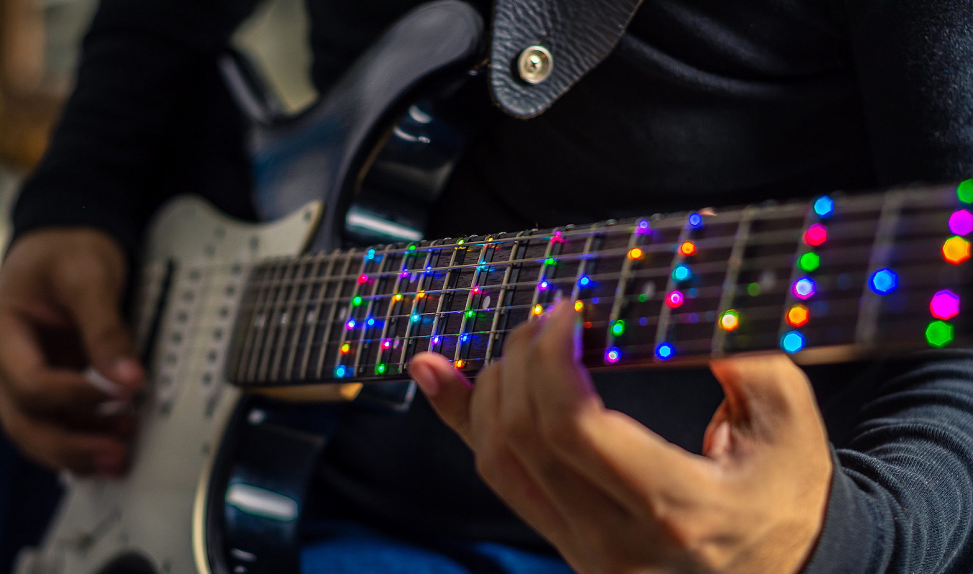
This week I primarily focused on performing an initial analysis of various aspects of the design. This consisted of determining how well a microphone will be able to pick up low frequency guitar notes, developing preliminary circuits for detecting strums, and measuring the latency required to write to WS2812 addressable LEDs.
For performing preliminary tests on picking up low frequency signals, I connected various electret microphones to an oscilloscope and observed their output waveforms when measuring a low frequency guitar note played from my computer. I found that using microphone breakouts with 50-100 times gain was more effective compared to creating an equivalent amplifier stage external to the microphone. The immediate amplification of the signal on a breakout board helped to eliminate most of the 60Hz noise that was introduced when routing the signal to an external amplifier stage. As such, if we choose to pursue a microphone-based approach, using a board such as Adafruits Electret Microphone Amplifier – MAX4466 with Adjustable Gain would be a good option. I did observe that low frequency notes were often drowned out by external noise and movement, which will significantly increase the complexity of a microphone-based approach for detecting strumming.
One observation I quickly made was that detecting a ~40Hz note in around 40ms using an FFT would be nearly impossible, since less than 2 periods of the signal would be collected. Additionally, measuring high frequency signals would require that the microprocessor is constantly sampling audio, which would take its attention away from driving the LEDs and talking to the Pi. As a result, Tushaar and I agreed that some amount of processing must be done on the analog side first. I experimented with various potential solutions and have had success with a 1st order low pass fed into an envelop detector, which is then fed into a differentiator circuit. The output of this system is a voltage spike that corresponds to sudden increases in the amplitude of sound waves. This would then be read by an interrupt on the microcontroller. This circuit has shown promise, but it will still detect sounds such as claps and output a signal. I hope that by putting the microphone in the resonant chamber of the guitar, or by tapping into some guitar’s built-in string pickup system, we can increase the signal-to-noise ratio of the system.
I also ran some basic tests on a strip of WS2812 addressable LEDs. From my testing I determined that writing to the ~56 LEDs that we will have should take around 2ms, which puts an upper limit of 500Hz on how fast we can sample audio signals.
This week I also worked on the design of the fretboard PCBs and picked out parts for them. They are mostly complete pending some slight sizing changes in order to best match the LED spacing to bass guitar string spacing. I hope to order the preliminary round of boards sometime this week. The design is made to be easily daisy-chainable. I decided to run two sets of power lines, one for the LEDs and one for the flip-flops driving the frets. I did this to avoid any ground-loop issues being caused by the voltage drop along the LED power wires. This does increase the number of wires that will be on the fretboard however, so it may be worth looking into consolidating for the final PCB run if this proves to be too many wires for comfort. The schematic and PCB were made in KiCad. I have not used KiCad in the past but I decided to make the switch to it due to the larger user community compared to my previous EDA tool.


