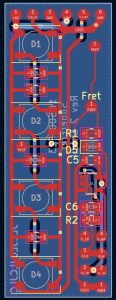
The main task I worked on at the beginning of this week was debugging the issue with the fretboard PCB flip flops. On Saturday night, I discovered that the filtering of the data lines seemed to resolve the issue, and on Sunday I soldered together 5 boards with the fix to test them. After using an oscilloscope to confirm the fix, I quickly updated the fretboard PCBs so they were ready to submit on Monday. The changes made were the addition of an RC filter on the data input to each flip flop. The issue this resolves is that without the filters, on a single clock edge an input signal could pass through one flip-flop and end up on the output of the next flip flop. Although according to the data sheet we should not have needed this RC circuit to satisfy hold time, the circuit appears to function now. The clock is also filtered, although the time constant for this filter is much lower and only serves the purpose of reducing ringing. This is done on the main PiHat PCB before distribution to the fretboard PCBs. The updated PCB schematic and layout are shown below.


This updated board was created in two sizes in order to better accommodate the changing spacing between the strings along the length of the guitar. The order was placed on Monday and should arrive in the middle of next week.
In order to test the functionality of my fretboard PCB fix, I wired the PCBs to my personal guitar temporarily and verified that the system could detect where I was placing my finger on the fretboard accurately. After verifying the PCBs worked, I passed the hardware and code off to Tushaar so he could integrate it into his firmware
Both the PiHat PCBs and DigiKey order arrived on Wednesday. On Wednesday night I assembled a PiHat PCB and began preliminary testing of the system. A completed board is shown below:

So far the following tests have been performed:
1. Voltage drop of power supply and PCB traces for the Pi and LEDs. The voltage at the Pi input was 4.9V at maximum current, which is above the Pi’s 4.75V minimum
2. Measuring thermals of the board when pulling the maximum expected current. Performed nominally
3. Testing the 3.3V to 5V logic level shifter for the NeoPixels. Performed nominally
4. Verifying the functionality of the buzzer. Performed nominally
5. Verifying powering the Teensy via USB does not attempt to power the Pi or LEDs, and that the Teensy can be connected via USB safely while also powering the system via a barrel jack. Performed nominally
A thermal image of the board while pulling 5A (the expected maximum is only 3A) through the Pi’s power traces:

As can be seen in this image, the maximum temperature reached by the trace is only 38C, which is completely reasonable for almost double the expected maximum current.
The final thing that I have been working on is planning the modification of the guitar and mounting of the electronics. I have begun creating CAD models and prints to support the PCBs, such as covers for the fretboard PCBs and a mount for the Pi and Pi Hat, which are shown below

Caption: A cover for the fretboard PCB that prevents the user from touching any exposed metal contacts

Caption: A preliminary case for the Pi and Pi Hat.
Our current plan is to insert the Pi and Pi Hat into the region of the guitar currently occupied by the built-in amp. I have managed to remove the amp and its internal connections in the guitar. We will be able to make a Pi case that directly mounts into this slot just like the original amplifier, allowing us to easily have access to the Pi for repairs and/or testing. We then plan to drill small holes in the side of the guitar to run wires with connectors on them to the fretboard and the end of the guitar strings

Caption: The hole in the guitar that the electronics will be inserted into
My progress is currently on schedule. The deadline Tushaar and I set for fixing the fretboard PCBs or moving to our alternative approach enabled us to stay on schedule and be confident we would not fall behind schedule. The fretboard PCBs should be in by the middle of next week, which will give me a bit of time to assemble them and install them. The main tasks I currently have left besides this will be the mechanical modification of the guitar.
This week I plan to begin carving out the channels for the fretboard PCBs and finalizing the mounts for the Pi-Hat PCB inside the guitar. I have been consulting with some of the shop-masters in Roboclub regarding the best way of accomplishing this task safely and efficiently. I will also be working on the assembly and testing of the fretboard PCBs when they arrive this week
