Team Status Report for 11/18/2023

The biggest risk that we are currently facing is the ambiguity over the time synchronization between the website and the guitar. Since both of them are displaying to the user the song at the same time, it is crucial to have them synced up to a reasonable amount. Thankfully, based on early testing, the delay between when the website inputs a query and when the backend receives the query over local wifi is small enough for the user to not notice. However, if the wifi gets slow and causes the connection delay to increase, then it is possible that the website could become completely detached from the guitar during the song. So we decided that the guitar timing information will be calculated on the teensy itself instead of sending pulses to the webpage so that at least the statistics will be correct for the users playing even if the website is delayed.

Progress is also on schedule with the Gantt charts presented during our Interim Demo.

This week our team made further progress in the integration of the whole super fret system. While Ashwin and Tushaar worked further on making the Raspberry Pi cooperate with the Teesy via Uart communication, Owen managed to carve out all the necessary channels in the fretboard of the bass guitar and applied all the PCBs.

Our team’s growth this semester has been evident in the strategic delegation of tasks and clear role understanding. Ashwin took charge of software development, Tushaar led firmware efforts, and Owen spearheaded hardware tasks. This division allowed us to capitalize on individual strengths and expertise. Effective communication was maintained through consistent updates and discussions on Slack, ensuring that everyone was informed and aligned with the project’s progress. Trust in each team member’s abilities enabled a collaborative environment, allowing us to efficiently tackle challenges and achieve our goals.

As a team, we have all learned how to better communicate the needs of our individual components of the project. We have learned that although we can each develop our components on our own, without constant communication, there will be issues with integration and ensuring that everyone has the same goals for the project. For example, Tushaar and Ashwin have had to be in constant communication to ensure that they both have the same views for each mode of the guitar. In the middle of the semester, we realized that we each had our own views for the guitar, so it was important for us to up our communication as a team and discuss our visions for the final product

Ashwin’s Status Report for 11/18/2023

This week I focused the majority of my time on the integration of the Raspberry Pi and the Teensy microcontroller. This involved further development of the communication standard between the two devices. Initially, I tried to use the pretty midi python library to aid in the processing and transmission of the midi file. The processing itself included adjusting the timing of the notes played based on the speed the user wished to play the file at, and stripping the file of any unplayed instruments. However, after further inspection, we noticed that the library took too many liberties with the byte representation of the file making it difficult for the teensy to parse its data. So we decided to create our own format for sending the necessary data. We decided on this protocol:

Preamble: first 4 bytes of file, contains length of file including length bytes
Each entry represents a note and is 5 bytes:
First 4 bytes: start time of note in millis
Last byte: bits 0-3 are fret, 4-5 are string

Using these rules, the teensy will be able to parse the data with much less complexity. This method was implemented on the Raspberry Pi using Uart.

This progress on the Uart communication puts me on track for the schedule we decided. For the next week, I want to continue to work on the communication between the pi and the teensy. Now the teensy should send back information to the pi about the user input. In order to implement this, we will need to define another protocol over Uart to send packets of information containing the time the user played a strum and whether the note was correct or not. In the future the Pi will use this data to generate statistics of the user’s playing and display on the website.

Owen’s Status Update for 11/18/2023

This week, I worked on a wide variety of tasks. These tasks included:

  • A board/program to test the assembled PCBs
  • Redesigning 3D printed covers for the fretboard PCBs
  • Carving out the channels in the guitar fretboard
  • Connecting the fretboard PCBs together
  • Connecting the Pi Hat PCB to the guitar strings, pick, and fretboard PCBs
  • Testing the hardware with Tushaar
  • Designing a 3D printed cover to protect the wires on the bottom of the guitar


Starting with the testing of the PCBs, this was done since the new PCBs featured the fix required for the D-flip-flops.

Shown above is a perfboard with header pins mounted to it. In the absence of proper pogo pins, I angled the headers at around 45 degrees to allow the pins to firmly contact the fretboard PCB. A Raspberry Pi Pico ran a series of tests on the D-flip-flops, providing a series of clock and data inputs and reading the output. The results of the tests were then displayed on the fretboard LEDs, which doubled as a verification of the LED functionality. Not including the time required to assemble the tester, this allowed for all of the boards to be tested in only around 5 minutes. The tester did properly find one soldering issue on a board, likely saving quite a bit of time worth of debugging if we had proceeded without testing.


While preparing to mount the boards, I also designed a cover for the PCBs. Our previous plan was to conformal coat the boards, but that would mean the user is still pressing onto an uneven surface. With a cover for the PCB, this prevents the user from touching the electronics and gives them a flat surface to press on. The design for the covers is shown above

Once the boards were assembled and ready, I began carving out the channels in the guitar. This was ultimately done with files and a dremel and was quite time-consuming. Tushaar was able to help out and do around 6-7 of the channels while I began soldering the fretboard PCBs together. There were a handful of mishaps while performing the carving. These included knocking off the guitar nut (the part that guides the strings at the top of the guitar) and breaking off a fret. Both of these were able to be fixed with very little evidence of repair.


To connect the PCBs together, I used 30 AWG wire-wrap wire and 26 AWG silicone wire. The D-flip-flop connections were done with thee 30 AWG wire due to the low current required. While not entirely necessary, the 4 wires between each fret were bundled together with heatshrink. These connections are shown above. The LED connections were done with 26 AWG wire due the higher current required.

To connect the Pi to the strings, pick, and fretboard PCBs, I used numerous banana plugs. Banana plugs were likely not the best choice of connector since they need to be done individually, but I did not have any JST connectors on hand. These banana connectors enable the rapid connection of the Pi/Pi-Hat to the rest of the guitar and enable it to be removed for repairs if needed. Holes were drilled in strategic locations around the guitar to route wires through, allowing for external wiring to be minimized.

Once the guitar was assembled, Tushaar and I used Ashwin’s webapp to upload songs to the Teensy and verify the functionality of all the LEDs and the finger placement sensors. We tested a variety of MIDI files and were able to get the firmware to a point where the training mode is almost complete from a hardware and firmware perspective.

One issue we did have was with the wires along the bottom of the guitar being sensitive to being moved, which is not ideal considering the user will be moving their hands up and down the guitar fretboard. We had this disconnect one of the 30 AWG wire connections and break the fret sensors. To resolve this, I designed a 3D printed device to cover the wires and protect them, with the added benefit of making the guitar more comfortable. The CAD model for this is shown below

This was then attached to the guitar, as shown below

So far this has proven quite effective at protecting the wires on the guitar and cleaning up the overall look of the guitar.

I am currently on schedule and my main tasks for next week will be performing the required hardware testing and verification and installing the PCB covers. We have held off on the covers while verifying functionality since placing the covers on will make repairs significantly more difficult.

My main deliverables for next week will be results for some of the hardware testing and the guitar fret covers installed. I also may work on some stretch goals, including adding the option to battery power the device. As discussed previously, for safety reasons we have no intention of implementing a charging circuit for an internal battery. Charging is when lithium batteries are most likely to combust, so removing charging from the equation makes battery power much safer. This would mainly be a quality-of-life feature for demoing, as it would remove the need to be tethered to an outlet. When testing though, Tushaar and I did not have any problems with the wall adapter, so this remains a perfectly viable solution for powering the device.


Tushaar’s Status Report for 11/18/2023

This week, I worked on 2 main tasks:

  1. Integrating the embedded system with Ashwin’s RPi and web app. We uncovered a few quirks of the User Interface.
  2. Helped Owen integrate the final fretboard PCBs onto the real guitar

I worked with Ashwin and Owen to integrate the embedded electronics as the “glue” between the web app and the electronics. I worked with Ashwin to flesh out how the restart, start, and pause signals would work, and it worked with the Pi and Teeny. We also uncovered an issue with the MIDI library Ashwin was using to parse the MIDI file, creating different outputs than my existing MIDI parsing code on the embedded side was expecting. After realizing the Teensy doesn’t care about the MIDI file, it just the locations and timing of notes on the fretboard, we transitioned from having the Pi send a MIDI file to instead sending a list of times and (fret, string) coordinates of where along the fretboard a note should be played. This also eliminated the need for the Teensy to run Ashwin’s note-to-fretboard coordinate algorithm on the Teensy. This change has been implemented, and the RPi can successfully send the coordinate and timing information over UART  to the Teensy. This works from start to end: a user can upload a MIDI file to the web app, and the RPi can convert that to a list of coordinates, which the Teensy can successfully receive and parse. Overall, this change resulted in significant simplification of the embedded code.  Furthermore, I refactored the embedded code to be in different files to organize it and make it easier to change and edit.

I also removed the assertion that would fail when the user was done with a song in Training mode, becuase it was unnecessary. Now, the system correctly loops back to the beginning WAIT_FOR_START state once the user experience is done (at least in training mode).

I made the color of LEDs on the fretboards light up with the same color as the notes on the web app:

I started the week by transitioning from having the Teensy4.1 on the breadboard to being on the PiHat PCB and controlling the LEDs and Flip Flops using the PiHat.


Later in the week, I worked with Owen to integrate the final fretboard PCBs on the guitar. I helped Owen carve channels in the guitar’s fretboard to keep the fretboard PCBs recessed:

I also soldered some wires between the PCBs to connect them together:


Now, we can take a MIDI file from the internet, upload it to the web app, and have the Teensy conduct the User Experience in Training mode on the actual guitar with the final fretboard PCBs!


Tushaar’s Status Report for 11/11/2023

This week I worked on several tasks:

  1. Testing and verifying the training mode of the user experience
  2. Integrating more interrupts from the RPi with Ashwin
  3. Modifying the state machine
  4. Starting to move from the breadboard to the more final Pi Hat PCB

I tested the training mode in the user experience, and I showed it off working correctly during the 3 demos this week. This is significant because it is an MVP for the embedded system. The only issue I ran into was an assertion mysteriously failing when the training mode finished. I will need to debug this.

Now that I am starting to integrate my embedded software with the RPi, I worked more closely with Ashwin and discussed, in detail, how we expect the user to use the system and what that means for communication between the RPi and Teensy. We realized a single pause interrupt can pause the system (when the pause signal rises) and resume (by checking when the pause signal falls). Ashwin implemented the pause interrupt on the RPi, and we tested to ensure the Teensy could respond to the interrupt.

We realized some incorrect and missing transitions in my state machine, so I added those in. The main changes were to the PAUSED state:

  1. Adding transitions from WAIT_FOR_STRUM and USER_EXPERIENCE to the initial WAIT_TO_START state upon receiving a restart interrupt. Previously, the only way to restart the state machine was to enter the PAUSED state and then transition to the initial state vis a restart interrupt, but this added an unnecessary visit to the PAUSED state; the state machine should reset to the initial state from any state upon receiving the restart interrupt.
  2. Redirecting the transition starting from the PAUSED state and ending in the WAIT_FOR_STRUM state to instead end in the USER_EXPERIENCE state. We realized the previous way involved an unnecessary intermediate state transition, which would interrupt the user experience.
  3. Leaving the paused state based on the resume condition (pause signal falls) instead of based on a strum

This is the state machine before the changes:

After the changes:


Since Owen was able to finish the Pi Har PCB, I could use it to test if it can properly relay signals between the RPi and Teensy. I moved the Teensy from the breadboard to the Pi HAT, changed some pins, and got the Teensy receiving interrupts from the RPi. This is a good step towards integration.

This progress is on track. The main tasks left for me are:

  1.  Testing the continuous part of the user experience
  2. Computing statistics on the user’s performance and sending that to the RPi
  3. Writing code for the buzzer

ABET #6 says … An ability to develop and conduct appropriate experimentation, analyze and interpret data, and use engineering judgment to draw conclusions

Now that you are entering into the verification and validation phase of your project, provide a comprehensive update on what tests you have run or are planning to run.  In particular, how will you analyze the anticipated measured results to verify your contribution to the project meets the engineering design requirements or the use case requirements? 

I plan to write unit tests to verify the embedded software to ensure small modules work correctly. So far, I have been manually testing the interrupts to ensure the state machine works, but this is time-consuming, and having an automated way to test this would be nice.

Also, to verify strum detection and note detection, I plan to strum the guitar several times and have the system count how many times it believed a strum occurred. Same for note detection. On top of what we already mentioned in the design review, I realized there is another important test to run besides testing for the system detecting the correct note – we should also play the wrong note and ensure the system can tell that it is a wrong note. That way, we can test for false positives and false negatives.


Team Status Report for 11/11/2023

The most significant risk currently facing the project is the carving of channels into the fretboard. This is proving to be more difficult than initially expected. Owen is working with experienced machinists at Roboclub to determine the best way to accomplish this. We have a backup plan of carving the channels with a Dremel, although the quality of this will likely not be ideal due to the angle we will have to use the Dremel at.

No changes have been made to the system block diagram. Progress on software and firmware is going well and the electronics hardware is complete other than final assembly and testing.

Progress is also on schedule with the Gantt charts presented during our Interim Demo.

The main team progress this week was the testing of the Pi controlling the Teensy state machine via interrupts. This was done using the Pi-hat PCB, allowing us to confirm that the PCB allows for communication between the two boards and properly distributes power to both boards. Tushaar and Ashwin have continued their discussions regarding communication between the boards, such as the preprocessing of the MIDI file done on the Pi and the format in which statistics will be sent back to the Pi from the Teensy.

Team progress for this coming week will be the connecting of the new fretboard PCBs to the Pi Hat for testing of the LED control and D-flip-flop control. Further work on and testing of the Teensy-Pi communication will be performed as well, particularly on the UART communication of the song data from the Pi to the Teensy and the statistics reporting sent from the Teensy to the Pi.

Owen’s Status Report for 11/11/2023

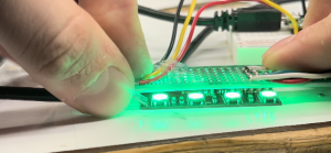
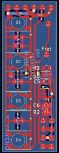
This week I primarily worked on the assembly of the fretboard PCBs and the mechanical modifications to the guitar. The fretboard PCBs arrived on Monday and I began assembly on Wednesday. Roboclub’s solder paste went bad so I began this process by hand soldering the boards. 7 of the smaller PCBs were done by hand. While not the most time-efficient, this was a valuable lesson in using tools such as SMD soldering tweezers and soldering small SOT-23-5 components without bridging pins. On Friday, I brought the boards and parts to the TechSpark PCB Fabrication Lab, where I did the assembly of the rest of the boards. This was done using the solder paste and reflow oven available in the Fab-Lab. After soldering the boards, I used the microscope to perform some touch-up work on some of the boards. In total, 8 of the smaller PCBs and 9 of the larger PCBs were assembled. These boards are shown below.

To validate the functionality of the boards, I created a perf-board with pins that would rest on the exposed pads of the board and run a series of automated tests on the board using an RPi Pico. However, I found that without pogo pins it was almost impossible to make contact with all the pads simultaneously, making testing impossible. I was able to test the functionality of the LEDs on all the boards using this system, but the D-flip flops could not be tested. I may be able to angle the header pins on the perf-board in such a way that they make better contact with the board. Getting this tool to function will allow us to be confident in the functionality of the boards before soldering them and mounting them to the fretboard.


The other main task that I have been working on this week is the mechanical modification of the guitar. The first task related to this was connecting wires to each string of the guitar so we can read the electrical stimulus on each string. A wire was connected to the termination point of each string via a solder joint and run into the body of the guitar through holes driller directly under the ends of the strings. This minimizes the amount of visible wiring needed on the guitar, which is one of our goals with the modifications. The image below shows the wires connected to each string before they are run into the guitar.

The wires terminate in bullet connectors, which will allow us to quickly connect and disconnect them from the main Pi Hat board when we need to remove it.

Progress has also been going well with the parts for mounting the Pi. I have 3D printed a new case for the Pi that will hold both it and the Pi Hat securely. I also 3D printed a new panel to cover the hole in the side of the guitar where the amp previously was, since the one I previously made did not fit very well.’

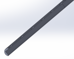
The main mechanical task, the carving of the fretboard channels, has not been going well. I attempted to cut one channel by hand, but this proved to be far too time-consuming. Roboclub’s mill was broken this weekend and the person working on repairing it was gone for the weekend, so I was unable to make progress with machining it. However, this week I hope to be able to get mill training and assistance in mounting the guitar to the mill. The backup plan would be to use a dremel, but the dremel is not ideal since it cannot be oriented in the desired way, meaning the channels would have a U shape, not rectangular. This could be filed down if desired, but would be very time-consuming.

In terms of schedule, I would have liked the channels to have been cut this weekend. Having the channels would have assisted in cutting wires to length between the fretboard PCBs, but I think that I can proceed with this without the channels. Tushaar is currently able to use the trainer fretboard to test his code, but I would like to switch over to testing on the actual guitar very soon. Tomorrow I will attempt to mount the Pi in the guitar and will test dremel-ing on the practice fretboard.

My main deliverables for this week will be the channels carved into the guitar and the PCBs soldered together and connected to the Pi.


Abet Question:

To verify that our system will meet the design and use case requirements we will be running numerous tests on our design.

For the hardware side of the project, these consist of:

  • Measuring current through the user
  • Verifying functionality of each LED and finger placement sensor
  • Determining the accuracy of strum detection
  • Determining latency from strum to Teensy updating state
  • Evaluating the comfort of the system

The verification of the fretboard PCB LEDs has been completed. This was done using an RPi Pico to cycle each NeoPixel through RGB values, allowing me to verify that each LED was functioning. I have also verified that we can source enough current to drive all of the LEDs at half brightness. This was discussed in my status report last week, in which I performed thermal testing of the power distribution on the Pi Hat. I found that while pulling 5A from the power supply, which is the maximum expected load, the voltage drop on the 5V line was acceptable and the traces did not overheat.

Very soon I will be measuring the current passed through the user when contacting a fret being driven high. We have tested this in the past with a multimeter that went down 0.1mA, but we will be collecting current measurements using a lab bench meter for additional accuracy. I will measure both the current passed through the skin under “normal” conditions for a handful of people as well as the short circuit current, which is indicative of the absolute highest current that could flow through the user, assuming they had 0 resistance. We have stringent requirements for these values, so it will be easy to determine if our device is meeting our requirements.

I have also verified the functionality of the strum detection using a series of 1/8th note strums at 100BPM and did not observe any missed or extraneous strums. This will be re-checked once the system is integrated onto the guitar. We will perform a series of 1/8 note strums at 100BPM on each string and count the number detected by the system, which will let us determine the system’s accuracy. We will then compare this result to our system requirements to evaluate the system.

Latency testing for strum-to-LED delay will be done by probing a string and the LED data line simultaneously with an oscilloscope. We will trigger on a rising edge on the voltage of the string, indicating the user is strumming, and will measure the time delay until the data line for the LEDs goes quiet. Our main Teensy loop is currently operating at well over 100Hz, including driving the LEDs and reading strums, so we expect no issues hitting out latency requirements.


Ashwin’s Status Report for 11/11/2023

This week I made significant progress on the web interface for the Superfret system. Now when you click on a playable file, the user is prompted to submit a short form which allows the user to customize their playing experience. This includes handy features like configuring the playback speed, choosing the specific track on the midi file, and choosing between training and performance modes. Training mode will wait for the user to strum each note before continuing, allowing the user to take their time learning the song. Performance mode will not pause the song unless the pause button is clicked. Once the submit button is clicked, the bass guitar will pop up on the screen along with the notes that begin to slide into place. In order to implement pausing in the system, I had to redesign how each note was drawn on the canvas. Initially, each note was catered to by a unique thread that sleeps until it is time to play the note. Now I draw each note at the start time onto one very tall canvas and slowly slide down the entire page of notes as one whole unit. This allowed me to very quickly implement pausing. Additionally, I added a note-worthy feature of playback audio. Now a user can click on the ‘toggle listening’ button to hear their MIDI file play out loud on the website. To implement the audio I used the Tone java script library to create a noise synthesizer (I gave it settings to make it sound like a bass). Then every time a note is played on the canvas, the synthesizer uses the midi file information to sound out the notes in real time.

For next week, I would like to work on the integration between the Pi and Teensy. To do this, I would need to makes sure the web interface logic agrees with the finite state machine of Teensy and we would need to test and set up the interrupt pins and the Uart connections.

Owen’s Status Report for 11/4/23

The main task I worked on at the beginning of this week was debugging the issue with the fretboard PCB flip flops. On Saturday night, I discovered that the filtering of the data lines seemed to resolve the issue, and on Sunday I soldered together 5 boards with the fix to test them. After using an oscilloscope to confirm the fix, I quickly updated the fretboard PCBs so they were ready to submit on Monday. The changes made were the addition of an RC filter on the data input to each flip flop. The issue this resolves is that without the filters, on a single clock edge an input signal could pass through one flip-flop and end up on the output of the next flip flop. Although according to the data sheet we should not have needed this RC circuit to satisfy hold time, the circuit appears to function now. The clock is also filtered, although the time constant for this filter is much lower and only serves the purpose of reducing ringing. This is done on the main PiHat PCB before distribution to the fretboard PCBs. The updated PCB schematic and layout are shown below.

This updated board was created in two sizes in order to better accommodate the changing spacing between the strings along the length of the guitar. The order was placed on Monday and should arrive in the middle of next week.

In order to test the functionality of my fretboard PCB fix, I wired the PCBs to  my personal guitar temporarily and verified that the system could detect where I was placing my finger on the fretboard accurately. After verifying the PCBs worked, I passed the hardware and code off to Tushaar so he could integrate it into his firmware

Both the PiHat PCBs and DigiKey order arrived on Wednesday. On Wednesday night I assembled a PiHat PCB and began preliminary testing of the system. A completed board is shown below:

So far the following tests have been performed:
1. Voltage drop of power supply and PCB traces for the Pi and LEDs. The voltage at the Pi input was 4.9V at maximum current, which is above the Pi’s 4.75V minimum

2. Measuring thermals of the board when pulling the maximum expected current. Performed nominally

3. Testing the 3.3V to 5V logic level shifter for the NeoPixels. Performed nominally

4. Verifying the functionality of the buzzer. Performed nominally

5. Verifying powering the Teensy via USB does not attempt to power the Pi or LEDs, and that the Teensy can be connected via USB safely while also powering the system via a barrel jack. Performed nominally

A thermal image of the board while pulling 5A (the expected maximum is only 3A) through the Pi’s power traces:

As can be seen in this image, the maximum temperature reached by the trace is only 38C, which is completely reasonable for almost double the expected maximum current.

The final thing that I have been working on is planning the modification of the guitar and mounting of the electronics. I have begun creating CAD models and prints to support the PCBs, such as covers for the fretboard PCBs and a mount for the Pi and Pi Hat, which are shown below

Caption: A cover for the fretboard PCB that prevents the user from touching any exposed metal contacts

Caption: A preliminary case for the Pi and Pi Hat.

Our current plan is to insert the Pi and Pi Hat into the region of the guitar currently occupied by the built-in amp. I have managed to remove the amp and its internal connections in the guitar. We will be able to make a Pi case that directly mounts into this slot just like the original amplifier, allowing us to easily have access to the Pi for repairs and/or testing. We then plan to drill small holes in the side of the guitar to run wires with connectors on them to the fretboard and the end of the guitar strings

Caption: The hole in the guitar that the electronics will be inserted into


My progress is currently on schedule. The deadline Tushaar and I set for fixing the fretboard PCBs or moving to our alternative approach enabled us to stay on schedule and be confident we would not fall behind schedule. The fretboard PCBs should be in by the middle of next week, which will give me a bit of time to assemble them and install them. The main tasks I currently have left besides this will be the mechanical modification of the guitar.

This week I plan to begin carving out the channels for the fretboard PCBs and finalizing the mounts for the Pi-Hat PCB inside the guitar. I have been consulting with some of the shop-masters in Roboclub regarding the best way of accomplishing this task safely and efficiently. I will also be working on the assembly and testing of the fretboard PCBs when they arrive this week


Tushaar’s Status Report for 11/4/2023

This past week, I worked on 2 main tasks:

  1. Writing the fretboard & strum detection software
  2. Implementing a first pass at the 2 training modes for the user experience.

After Owen could fix the fret detection hardware with RC filters on the digital lines, I wrote code to sample the fretboard and pick. The involved applying a voltage stimulus to each fret in a serial fashion, reading each of the 4 strings, and repeating 14 times. This whole process takes under 1 millisecond, which is good. The sampling is done every 10ms.

As for strum detection, we decided to use an electrified pick. The PGIO connected to the strings senses a high voltage when the pick contacts the string. This sampling is done every 10ms, and a “strum” is detected when the pick leaves the string (i.e. when the previous “strum-sample” detects the pick on the string but the current sample doesn’t) and it has been sufficiently long (10ms) since the last strum (this is software debouncing). Since the Teensy itself uses a GPIO pin to apply a voltage stimulus to the pick and reads the return signal on the strings with 4 GPIOs, there is no need for having a strum interrupt. So, I removed that interrupt.

After talking as a group, we have determined the user experience should consist of 2 selectable modes:  “TRAINING” and “CONTINUOUS” modes. In TRAINING mode, the system will wait for the user to play the lit-up note before lighting up the following note. Here, the user’s timing in playing the notes is not critical because the point of this mode is to show the user where the notes are, not when to play them. In CONTINUOUS mode, the system will not wait for the user to play a note; instead, it will continue flashing notes on the fretboard at the rate indicated by the MIDI file. The system will keep track of the time between when a note should’ve been played and when it was actually played, and store the difference as a statistic.

The following pictures show the code for the 2 training modes.

TRAINING mode:

CONTINUOUS mode:

Since Owen had to take the hardware to do hardware development with the newly arrived Pi-Hat PCB, I didn’t get a chance to test my code for the 2 user experience modes. But this is okay since I could still write the code, and hopefully, next time we meet, it will just be a debugging session instead of spending time writing the code in the first place.


Overall, I was able to recover from 2 tasks that slipped:

  1. The task “Able to read finger placement sensors on fretboard PCBs” is now finished
  2. The task “Able to read in strum signal” is now finished

Upcoming tasks include testing the 2 user modes and integrating the rest of the interrupts with Ashwin.