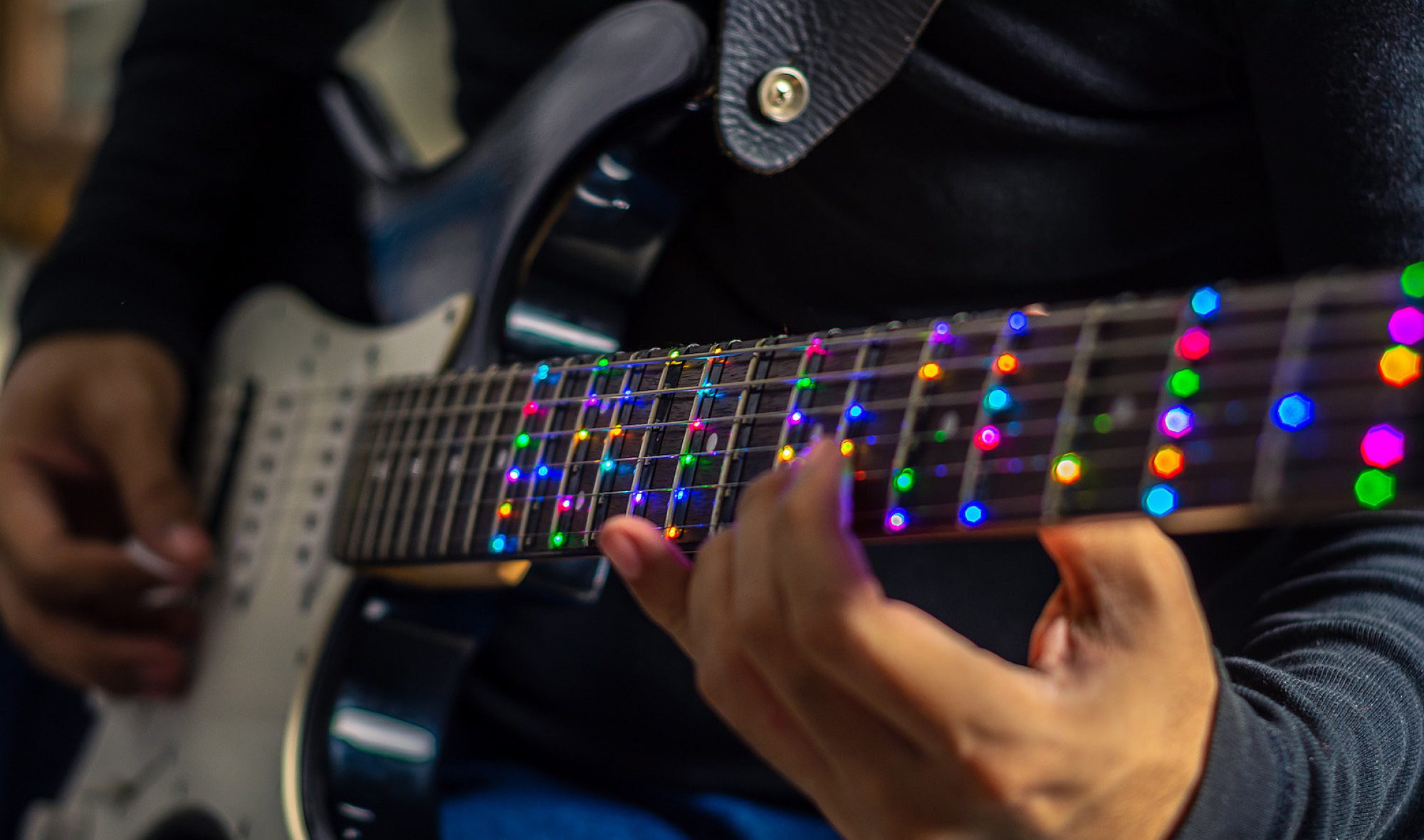
This week I primarily worked on the testing of the fret-detection using the fretboard PCBs. This has not gone smoothly and has taken up most of my time for the week. Besides this, the Pi-Hat PCB was tweaked slightly and ordered, along with the required parts from DigiKey.
While I did test the functionality of the fretboard PCBs shortly after assembling them, when Tushaar and I went to test the system with some basic string-fret switches that we made, we ran into some problems. The primary issue was that the output on the D-flip-flop seemed to be going high on some of the flip flops further down the shift register earlier than expected. Tushaar and I first noticed this on Tuesday night and spent from around 7pm to 11pm working on this. The main realizations made was the one stated previously, as well as determining that this issue occurred no matter what the clock speed. We also looked through the timing information on the flip-flop datasheet and ensured that we were not violating any parameters such as hold or setup time.
Before class on Wednesday, I hand soldered some extra D-flip flops to PCBs and tested them, and determined that they were working. Thus, for our Wednesday meeting, Tushaar and I focused on determining what the differences were in the two systems. We came up with the following:
1. The hand soldered boards did not have LEDs on them
2. The hand soldered boards used shorter wires connecting them together
3. The hand soldered boards did not have the current limiting resistor and accompanying diode on their output
4. The hand soldered boards were not put on a hot plate
Of these, we highly doubted 1 or 3 to be the cause. Our primary theory was that the flip-flops were damaged by the hot plate, so I removed the flip-flops from the non-working PCBs and hand soldered new flip-flops. This did not resolve the issue. Further testing of the original set of working hand soldered boards revealed that under certain conditions, I could cause outputs to appear one clock cycle earlier than expected. This was done by adding capacitance to the clock line, which I believe resulted in the output signal from the previous flip-flop arriving slightly before the clock edge instead of simultaneously. This resulted in the second flip-flop storing the value that was going into the first flip-flop’s input on the clock edge. I added a resistor and capacitor delay circuit to the data line and it appears to have solved the issue, although I have yet to do this to the fully soldered set of PCBs to confirm this works on them as well.
Tushaar and I have discussed contingency plans and have set a cut-off time for switching over to the contingency plan. The plan is to run 14 individual lines, one to each fret. We believe that by doing this with magnet wire, it would not be intrusive to the user at all. This approach requires numerous free GPIO pins on the Teensy. Almost as soon as the issue arose, I began working on revising the PCB to break out a handful more Teensy GPIO pins to ensure that we had enough for this plan. The board ordered on Thursday has these additional pins in place.
This weekend I plan to add the RC delay circuit in between each fretboard PCB to test this solution, and if it works, I will revise the PCBs and order them. If the solution does not work, I will also modify the PCBs accordingly and order them, as we have not found any issues with the LEDs on them.
One other thing that I worked on was a system to detect which string is strummed. This was done using a pick with an electrode on it and connecting the pick to the microcontroller via a flexible wire. This turned out to be extremely accurate for both detecting which string is strummed and when, making the strum detection circuit somewhat obsolete. I have found that especially as am amateur guitar player, I can accidentally create noises when moving my fingers that could trigger the strum detection circuitry. However, using the pick seems to be much more resilient to ignoring these extraneous noises, making it a more reliable solution.
Due to the fretboard PCB issues, we are behind schedule on them. We will be ordering them this week. Assembly will likely be faster than originally expected which alleviates some concern, but we may choose to use some of our budget to try and expedite the order. While waiting for the Pi Hat PCBs and fretboard PCBs, I will begin the mechanical modifications of the guitar, mainly planning the mounting of the Pi and determining the best method in which to carve channels for the fretboard PCBs. I believe that this will put me on schedule to mount the Pi and fretboard PCBs in a timely manner once they are received.
As mentioned previously, the main deliverables for this week will be ordering the fretboard PCBs and a full plan for the mechanical mounting of the PCBs and Pi, as well as some progress on this task.
