Tushaar’s Status Report for 10/28/23

I have finished implementing the state machine and the rest of the interrupts that it will take in. I also tested it with the shift register fret-detection but ran into issues with the fret detection not working. I spent several hours with Owen trying to debug it, and I tried a variety of things to try to rule out software as an issue. One attempt at this was adding delays (using delayMicroseconds() and delay() calls) in between the digitalWrite() calls that controlled the digital clock and data-in signals for the shift register in case they were changing too fast for the DFFs to register the signal. This did not help, and after viewing the signals on a scope and reviewing the code logic carefully, Owen and I decided the software was not the issue.

So, we were pretty sure it was a hardware issue, with the flip flops not propagating the data correctly through the shift register. We had several theories for why this could be:

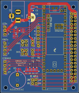
  1. The hot-plate method of soldering SMD components on the fret PCBs killed the D-Flip-Flop chips.
  2. We were damaging the chips with ESD
  3. We were running into setup/hold time issues
  4. The clock was ringing so much that the digital assumption broke down.

More details are documented in Owen’s status report, but the gist is that we don’t think the issue is 1 or 2. To have less ringing on the clock, I suggested adding an RC delay between the stages to allow for a smoother clock signal, and after Owen tested that out, the results seemed to improve. This may have helped 3 and/or 4.

As for the state machine, I implemented the final 2 interrupts (pause and restart) and the done signal. The “done” signal is asserted when the song finishes – when all notes in the MIDI file are read.

To start integrating the fret detection, I implemented sampling of the fretboard, but as described, I ran into issues with the shift register malfunctioning. The following images show the code for sampling the fretboard:

The clearShiftRegister() function ensures no voltage stimulus on the fretboard before we start reading. This is done by propagating a 0 through the fretboard twice for good measure. loadShiftRegister() loads a single 1 into the shift register, which is later propagated through the DFFs. The sampleFrets() method calls the previous 2 and does the “shifting” of the shift register by pulsing the clock and reading the GPIO pins connected to the strings (this is another task that I implemented this week). sampleFrets() is called periodically,  and when the “sample” contains an interesting value (a string is pressed down on a fret), the state machine prints a message for debugging.


This progress is on track. Despite the hardware side of the fret detection keeps slipping, the software part is back on track after slipping last week. Going forward, we must build confidence in the RC delay solution or pivot away from a shift register and use 14 individual GPIOs to provide electrical stimuli to the frets.

Next week, I will need to work on the 2 different user modes – “training” mode, where the system waits for the user to play a note before moving onto the next note, and “continuous” mode, where the system keeps flashing LEDs according to the timing set in the MIDI file even if the user can’t keep up. I have also realized that the time specified in the MIDI file for holding a note is meaningless for a guitar because there isn’t a concept of “holding” a note for a duration on a guitar. Thus, the timing I care about is the duration from starting a note to starting the following note, as opposed to knowing both the duration from starting a note to ending it and the duration between ending a note and starting the next note. This gives more clarify on how I will implement the 2 different playing modes.

Team Status Report for 10/28/23

Currently, the most significant risk to the project is the functionality of the fretboard PCBs used for finger placement sensing. The issue is that the D-flip-flop shift register is not working as expected and as such, the finger placement sensors are not functioning. Tushaar and Owen have spent around 6 hours working together to resolve the issue, along with Owen working to solder new boards and resolder the existing ones to little avail. Owen believes that he may have a fix for it, but if not, we have a contingency plan for running individual wires to each fret. While not ideal, this approach is simpler and less error-prone. The Pi Hat PCB has been designed with enough GPIO pins that will be feasible. Since the fretboard PCBs have been delayed due to this, we may use some budget to have shipping on them expedited in to ensure that we have sufficient time for assembly of the system.

The main change to the system block diagram is that we are planning on shifting the strum detection from an audio-based system to detecting the electrical contact between the pick and the string. This addresses the previous issue of being able to detect which string is strummed and increases the accuracy of the strum detection system by reducing false-positive detection of strums. This will also reduce the complexity of the system by enabling the firmware to not handle the strumming as an interrupt, but rather read it in during the system’s main loop.

In terms of schedule changes, the main change is that Tushaar and Owen are slightly delayed by the issues with the fretboard finger sensing. The cutoff time for switching to the contingency plan of class time on Monday will enable us to stay on track though, especially considering the contingency plan is easy to execute both in hardware and firmware.

The main progress this week was Owen ordering the Pi Hat board, Ashwin making progress on the web interface displaying notes, and Tushaar making progress on the Teensy state machine.

Ashwin’s Status Report for 10/28/2023

In the last couple of weeks, I have made further progress in the development of the software components of the superfret system. Firstly, I developed a Uart driver that allows the web app being hosted on the Raspberry Pi to communicate directly to the Teensy microcontroller via a simple interface. We have additionally conducted rudimentary tests to check the communication and were able to successfully send entire midi files as well as interrupt signals using the midi driver. Tasks that are left on this component include refining the communication standard more as the hardware develops to enable seamless communication and synchronization between the two processors. This puts me on track with our projected schedule. Additionally, I began working on the dynamic scrolling note feed since our team determined it would be a very nice feature to have from the perspective of our users. This is a much more involved task so I broke it down into separate categories:
– Display Alignment
– Display synchronization
– Midi file parsing and sending
– Translation from note number to fret and string number
Currently, I was able to make significant progress in the Display alignment category. This task involved creating a dynamic webpage with moving shapes. I implemented this behavior using HTML canvas graphics manipulated by frontend JavaScript. I created a demo webpage that helped debug the page and showcases its functionality:

For next week I hope to have made significant progress on the dynamic guitar display. Progress in any of the categories for this task will help improve its functionality and help determine the viability of the feature.

Owen’s Status Report for 10/28/23

This week I primarily worked on the testing of the fret-detection using the fretboard PCBs. This has not gone smoothly and has taken up most of my time for the week. Besides this, the Pi-Hat PCB was tweaked slightly and ordered, along with the required parts from DigiKey.

While I did test the functionality of the fretboard PCBs shortly after assembling them, when Tushaar and I went to test the system with some basic string-fret switches that we made, we ran into some problems. The primary issue was that the output on the D-flip-flop seemed to be going high on some of the flip flops further down the shift register earlier than expected. Tushaar and I first noticed this on Tuesday night and spent from around 7pm to 11pm working on this. The main realizations made was the one stated previously, as well as determining that this issue occurred no matter what the clock speed. We also looked through the timing information on the flip-flop datasheet and ensured that we were not violating any parameters such as hold or setup time.

Before class on Wednesday, I hand soldered some extra D-flip flops to PCBs and tested them, and determined that they were working. Thus, for our Wednesday meeting, Tushaar and I focused on determining what the differences were in the two systems. We came up with the following:
1. The hand soldered boards did not have LEDs on them

2. The hand soldered boards used shorter wires connecting them together

3. The hand soldered boards did not have the current limiting resistor and accompanying diode on their output

4. The hand soldered boards were not put on a hot plate

Of these, we highly doubted 1 or 3 to be the cause. Our primary theory was that the flip-flops were damaged by the hot plate, so I removed the flip-flops from the non-working PCBs and hand soldered new flip-flops. This did not resolve the issue. Further testing of the original set of working hand soldered boards revealed that under certain conditions, I could cause outputs to appear one clock cycle earlier than expected. This was done by adding capacitance to the clock line, which I believe resulted in the output signal from the previous flip-flop arriving slightly before the clock edge instead of simultaneously. This resulted in the second flip-flop storing the value that was going into the first flip-flop’s input on the clock edge. I added a resistor and capacitor delay circuit to the data line and it appears to have solved the issue, although I have yet to do this to the fully soldered set of PCBs to confirm this works on them as well.

Tushaar and I have discussed contingency plans and have set a cut-off time for switching over to the contingency plan. The plan is to run 14 individual lines, one to each fret. We believe that by doing this with magnet wire, it would not be intrusive to the user at all. This approach requires numerous free GPIO pins on the Teensy. Almost as soon as the issue arose, I began working on revising the PCB to break out a handful more Teensy GPIO pins to ensure that we had enough for this plan. The board ordered on Thursday has these additional pins in place.

This weekend I plan to add the RC delay circuit in between each fretboard PCB to test this solution, and if it works, I will revise the PCBs and order them. If the solution does not work, I will also modify the PCBs accordingly and order them, as we have not found any issues with the LEDs on them.

One other thing that I worked on was a system to detect which string is strummed. This was done using a pick with an electrode on it and connecting the pick to the microcontroller via a flexible wire. This turned out to be extremely accurate for both detecting which string is strummed and when, making the strum detection circuit somewhat obsolete. I have found that especially as am amateur guitar player, I can accidentally create noises when moving my fingers that could trigger the strum detection circuitry. However, using the pick seems to be much more resilient to ignoring these extraneous noises, making it a more reliable solution.


Due to the fretboard PCB issues, we are behind schedule on them. We will be ordering them this week. Assembly will likely be faster than originally expected which alleviates some concern, but we may choose to use some of our budget to try and expedite the order. While waiting for the Pi Hat PCBs and fretboard PCBs, I will begin the mechanical modifications of the guitar, mainly planning the mounting of the Pi and determining the best method in which to carve channels for the fretboard PCBs. I believe that this will put me on schedule to mount the Pi and fretboard PCBs in a timely manner once they are received.

As mentioned previously, the main deliverables for this week will be ordering the fretboard PCBs and a full plan for the mechanical mounting of the PCBs and Pi, as well as some progress on this task.

Tushaar’s Status Report for 10/21/23

Since the last update, I was able to:

  1. Continue implementing the state machine and integrate it with the MIDI file receiving and parsing code
  2. Implement the necessary interrupts for the state transitions
  3. Verify that the interrupts trigger the state transitions using an analog circuit

After talking with the teammates more about how the user experience will work, we decided the RPI will do light parsing of the MIDI file (to strip out unnecessary information that the Teensy doesn’t care about), so the Teesny only needs to parse the note and timing info.

Since the last update, I included a much more final version of the state machine, including support for the “file_transmission”  and “pause” interrupts, which will eventually originate from the RPi. Implementing these 2 interrupts was challenging due to being rusty with the Arduino ecosystem, but those 2 alone account for half of all the state transitions. The next interrupts will be easier given that I already know how to do this now.

The above image shows the 2 interrupts I implemented and how they affect the state machine. The following image shows how code is executed in the main run loop based on the state stored in the FSM:

This picture also shows that I have integrated the MIDI file parsing code into the body of the state machine. This unifies 2 previously disparate bits of code.

Since I didn’t have easy access to the RPi (Ashwin is using it for his development), I had to figure out a way to mimic interrupts from the RPI. Since plugging a wire in and out of a breadboard rail will give multiple edges, it was not feasible to generate clean interrupts. Instead, I resorted to a purely analog way of generating the interrupt. By taking the signal that would otherwise contain multiple edges and feeding it through a simple RC low pass filter with a time constant on the order of 1 millisecond (10k resistor + 100nF capacitor), I can achieve “analog debouncing.”

The following picture shows a bank of such RC filters so I can mimic multiple interrupts. The “paper flags” indicate the name of the interrupt being simulated. The yellow wires that arch over are plugged into and out of the breadboard power rails to create rising and falling edges. Pull-down resistors (not pictured) pull the interrupt pins down to 0V so they are not floating when the yellow wires are not connected to either logic level.


This progress is on track as I finalize the structure and implementation of the code. The next big tasks are verifying fret detection (this has actually slipped) and creating the user experience modes (scale + song).


As you’ve now established a set of sub-systems necessary to implement your project, what new tools are you looking into learning so you are able to accomplish your planned tasks?

As I integrate more with Ashwin’s web-app, I might need to learn about his code. This may involve learning web-app frameworks in Python (something I have never done before) so I can understand what his code does and how it can easily input the data that will flow between it and the Teensy. Also, since we decided to offload some parsing onto the RPI, I may need to learn about low-lever byte manipulation libraries in Python, so I can communicate with Ashwin about how he can transition my existing C++ parsing code to Python. I don’t have much experience with such python libraries, so that will be new.

Team Status Report for 10/21/23

The most significant risks we are facing with our project are still detecting which string is strummed and also indicating to the user how long to play a note/when the next note is coming.

The solution we currently plan to implement for determining which string is strummed is to put a metal contact on the guitar pick and detect when it is in contact with one of the strings the same way the finger placement is detected. Owen has constructed some guitar picks with metal tips that we can test out for this purpose, as shown below

For the other main risk, we currently have plans to indicate the tempo to the user, but songs have rests and notes that last more than 1 beat, so we need an indication to users regarding when to play a note. One potential solution to this is to have a set of LEDs on the fretboard not dedicated to showing you where to place your fingers, but showing you when to play the next note in the song.

The main change to the system block diagram has been that the Pi-Hat PCB will no longer contain the strum-detection circuitry, and this will instead be done on a perfboard. This will enable more flexibility and modification to the circuit in the future and reduces the risk of an issue affecting the circuit. The strum detection circuitry will interact with the Teensy via pads on the Pi-Hat

There have been no changes in the schedule and progress is on track.

The main team accomplishments this week consisted of Owen assembling the fretboard PCBs, which Tushaar was then able to control and light up to the rhythm of Twinkle Twinkle Little Star. The rhythm was determined by a MIDI file, which Tushaar and Ashwin are able to communicate between the Pi and Teensy. This week, we hope to test the finger placement sensing and perform further integration of the Pi and Teensy communication.

This image shows 3 of the 5 assembled fretboard PCBs being controlled by a microcontroller to light up in a pattern.

Owen’s Status Report for 10/21/23

As you’ve now established a set of sub-systems necessary to implement your project, what new tools are you looking into learning so you are able to accomplish your planned tasks?

To accomplish the hardware tasks planned for this project, I have had to learn how to use various software tools, along with a handful of physical tools.

The main software tool that I have been learning to design the PCBs for the project has been KiCAD. In the past, I have worked with Altium and EasyEDA but I wanted to branch out and learn more tools. EasyEDA served me well for a handful of designs but I wanted slightly more professional software, and one with a larger community. Although I also have experience with Altium, I personally do not enjoy it for personal projects, and I wanted to familiarize myself with the workflow associated with software other than Altium.  Learning KiCAD primarily consisted of familiarizing myself with the location of various options and menus, such as customizing the DRC rules to match those of JLCPCB. I also had the opportunity to learn how to import symbols from Digikey and create/import footprints for parts. In the past I have either been able to find parts in the built-in catalog or in my company’s parts library, so it was good to learn the process of creating my own parts. I also had to learn how to create a precise board outline and mounting holes, which I have not had experience with in the past. In previous projects, I have just created a board and then created a mount to fit it in CAD, but for this project, my boards must mount onto existing hardware such as a Raspberry Pi. I have also been learning new skills in Arduino to test my hardware. For example, I have learned how to use the NeoPixel library to run the LEDs on the PCBs as well as learned how to detect interrupts with the Teensy and operate the D-flip-flops on the PCBs in order to accelerate my testing.

In terms of physical tools, I have been learning to work with PCB stencils and surface mount soldering. I have dealt with some surface mount soldering of 0402-0805 resistors and capacitors, but not in large quantities or anything more complex. Additionally, in the past I have always hand-soldered these parts. However, since we need around 14-15 of the fretboard PCBs, I am learning how to use PCB stencils, solder paste, and hot plates in order to expedite the soldering process. I have also been learning about a variety of sensors in our quest to find solutions to some of our sensing problems. This consists of learning how capacitive touch sensors work, as well as how the inductive and piezoelectric pickups used in many guitars function.

For the future, I am mainly interested in learning how MIDI files work a bit more so that I am more familiar with the work being done by software and firmware and can better integrate the hardware with these systems.

Weekly Update

This week I primarily worked on the assembly and testing of the fretboard PCBs and the design of the Pi-Hat.

The assembly of the fretboard PCBs went well. This was done using the SMD stencil and a hot plate. In total 5 were assembled for Tushaar to use for testing. The pad for the current limiting resistor was replaced with a surface mount diode. The resistor will be added between the fret pad and the fret, so the safety of the system is not compromised by this. The functionality of the LEDs was tested, along with the D-flip-flops used for driving each fret high.

Top: One of the fretboard PCBs on a hot plate
Bottom: Initial tests of the LEDs on the fretboard PCB

There are a couple of changes that need to be made to the PCB, most of which were implemented this week. The first change is adding a pad for the SMD diode in series with the current limiting resistor. The next change was to switch out the through-hole pads with pads on just the surface of the PCB. If solder flows though the through-hole pad it can result in an uneven bottom of the board, making mounting it more difficult. The next change was to make the PCB narrower by around 1.5mm. The initial measurements of the PCB were taken from a photo, and as a result, the PCB is slightly too wide to fit next to the 14th fret. The final change that needs to be made is to adjust the spacing of the LEDs. Currently, the spacing is reasonable for the middle of the guitar, but by making a few variants of the board, we can better match the spacing of the strings. The updated board layout is shown below

D1-D4 on the left are the LEDs. The top pads are the connections for the LEDs, and the bottom right ones are for the fret-driving flip-flop, which is on the right side of the board.

This week I also worked on the Pi-Hat PCB. The main change to the plan for the PCB is to offload the strum detection to a perfboard. The circuit needs a lot of tuning and this can be better done on a perfboard. This reduces the risk of the strum detection not functioning.
The PCB consists of the following components:

  1. A 5V barrel jack connector with filter capacitors. The 5V directly powers the Pi and LEDs and the Teensy is powered through a Schottky diode. This prevents backpowering the micro USB port on the Teensy, allowing the Teensy to be plugged into a computer while the system is also powered. It also prevents the USB port from attempting to drive the LEDs, which would draw too much current.
  2. The Teensy 4.1. A handful of the I/Os are sent directly to pads for future needs. 4 pads have external pull-down resistors and will be connected to the strings of the guitar. 10 of the I/O are routed directly to Pi GPIO pins allowing for communication. There are currently no plans to use all 10 of these, but this enables expansion in the future.
  3. A header to mate directly to the header on the Pi. In addition to the GPIOs routed to the Teensy, 4 I/O pins are broken out to pads for future use
  4. An active buzzer driven off a Teensy PWM pin. We can PWM the power to the buzzer to control the volume of the buzzer. A resistor pad is also included for current limiting the buzzer, although the current plan is to place a jumper on this pad.
  5. A 3.3V to 5V logic level converter to convert the 3.3V signal from the Teensy to a 5V signal for the LEDs. This may or may not be needed according to testing, but according to the LED datasheet the signal should be at least 3.6v

The current layout of the board is shown above. The Pi header is on the right side and the Teensy is the component to the left of the headers. The top left is the power barrel jack. Along the left side is I/O and at the bottom of the board is the buzzer.

For the most part my progress is on track. The fretboard PCBs still need their LED spacing revised, but this can be done fairly quickly once the desired spacing is determined. The Pi-Hat PCB design is ahead of schedule. These boards will likely be ready to be sent out in the same order, reducing the shipping costs incurred. The PCB assembly turned out to be faster than I expected, so this will not take as long as indicated on the schedule.

The DigiKey cart has also been compiled for the PCB orders, so that can be sent out this week.

The final thing that I worked on was the strum detection circuitry. It is mostly working on a breadboard so I hope to perform some final testing of that before soldering it up.

My main deliverables for next week will be ordering the PCBs and sending out the DigiKey order. I also hope to solder the strum detection circuit on perfboard.

Team Status Report for 10/7/23

The most significant risk for the project is still the sensing of which string was strummed. We are confident in our ability to detect strumming, but which string is a much greater challenge. We have been brainstorming solutions to this issue, including using a capacitive touch sensor on each string to sense when the user touches them. The main issue with this approach is that it would falsely report values if the user was resting their fingers on strings other than the one being strummed. Additionally, the sensors are often slow to react and would not work well with the strings being driven to 0 and 3.3V. We have also thought about using inductive pickups under the strings. The main challenge with this solution so far has been finding pickups that individually sense each string instead of combining the signals together. To mitigate risks, we have come up with a solution that will work but is slightly more intrusive for the user. This solution would involve applying a voltage to a metal guitar pick. This would occur when all the D-flip-flops are outputting low, so if the pick contacted a string, the string would be brought from 0V to 3.3V. This would allow us to detect where the pic is. Combining this with the strum detection, this will allow us to determine when the user strums and what string is strummed.


Design Presentation block diagram:

The most significant change made to our design presentation block diagram is that some of the MIDI parsing will likely be switched to the Teensy. This is because the note and timing data needs to be sent to the Teensy somehow, and it will be easier to do this using an existing format rather than making our own method of conveying this information. The Pi will potentially also be performing some MIDI parsing in order to display to the user things like where they are in a song, what notes they are getting wrong, etc., but the raw MIDI file will also be sent to the Teensy. Since Ashwin is becoming more confident with Django and HTML/CSS, we are expanding the webapp to include visuals indicating the user’s performance, such as if they are incorrectly timing notes, what percentage of notes they fingered correctly, etc.

The most significant change in the schedule is that the assembly and testing of the PCBs for the fretboard will not be able to start until likely Monday since the shipping was delayed slightly. Ideally by Tuesday at least one of the boards will be ready so that Tushaar can help test it. Progress on the UART communication between the Teensy and Pi, along with the interrupts, is ahead of schedule, which should hopefully allow for the user interface and experience to receive additional attention at the end of the semester.

Overall team progress consists of Ashwin being able to send MIDI files to the Teensy with the press of a button on the web app. There is occasionally some loss during this transfer so we need to determine the cause of this. Tushaar is able to light up LEDs in response to a MIDI file on a set of RGB LEDs, and this will hopefully be able to be tested on the fretboard PCBs when Owen gets them assembled. The guitar should be in by Monday so we expect to be able to verify the strum detection concept and the sizing of the PCBs very soon.

The main goals for this week are to continue working on the UART communication between the Pi and Teensy, establish more of the interrupts used to control the Teensy, and for Owen to work on a PCB that will connect the Teensy, Pi, and I/O in accordance with the needs of Tushaar and Ashwin.

Weekly Status Report Question:

While developing a more detailed plan of our implementation for the design presentation, our team used numerous principles of science, engineering, and mathematics. While developing plans for our individual components of the project, it was important to keep the principle of integration in mind. While we each have an area of expertise on the project, each of our systems will be interacting with each other’s. For example, the fretboard PCB board PCBs need to be able to interact with the 3.3V logic level of the Teensy, which will allow for the firmware on the Teensy to control the LEDs and read from the fretboard. Similarly, the firmware on the Teensy will be playing the songs, but in order to do this, it needs the actual data for the songs to be sent by the Pi. Similarly, the Pi will be displaying statistics on the webapp, but in order to do this, it needs to be able to receive and interpret the data sent by the Teensy. As a result of these factors, it has been absolutely essential that our team is in constant communication regarding design choices and intentions. Otherwise, when we go to assemble our final product, the systems will not be able to interact with each other properly. Our weekly meetings allow us to take what we have been working on independently, explain it to each other, and work on integrating the systems together. This week, we were able to take Ashwin’s web app interface to send interrupts to the Teensy, which Tushaar was able to read and react to. We were also able to test and debug the UART communication between the Pi and Teensy.

Another principle that we used extensively this week was management. In order to ensure the smooth completion of the project, it is essential that everyone knows what tasks they are responsible for, when/how it will be completed, and how it will affect them. This involves constant communication between team members to ensure that everyone is on the same page. Our weekly meetings help us to recap with each other how progress is going so we can verify that tasks are being completed. They also allow us to talk through any potential modifications that need to be made to our plans/tasks for the future. This allows us to be confident that we will be able to successfully navigate around any unexpected challenges or setbacks and end the semester with a completed project.

Ashwin’s Status Report for 10/7

This Week I worked more on the website in order to implement the backend functionality that would eventually allow us to send MIDI files to the guitar via a web interface as well as stop and start songs. The work primarily consisted of creating database endpoints and linking the front end to the backend via Javascript.  More specifically:

Here is the website without any songs in the database (we would have pre-downloaded files for final user experience). Clicking on the add file button allows you to add a file:

Here you can designate a name, a file, and whether it is a song or a scale file.

After you click submit, the file will appear in the list that you chose. This is significant as it means the file is stored on the Pi itself allowing us to parse it and display it on the guitar in real-time. You can then delete the file if you no longer wish to use it or start the file to theoretically begin the song on the guitar.

Upon clicking the start button, the webpage freezes and a popup appears indicating that a session is in progress. The user can then stop the song at any time using the stop button.

This completes most of the basic functionality for the GUI which puts me on schedule. However, in the future, we plan to implement a scrolling guitar dynamic display (like that from Guitar Hero) on the website. This would allow the user to refer to both the guitar and the website for guidance. For next week, I hope to implement a UART driver that allows the Raspberry Pi to communicate with the microcontroller.


Tushaar’s Status Report for 10/7/23

This week, I accomplished 4 main tasks:

  1. Rehearsed and presented our design review
  2. Wrote code for the Teensy to parse a MIDI file and light up LEDs according to the rhythm of Twinkle Twinkle Little Star.
  3. Able to get the Teensy to read in a MIDI file from the RPi
  4. Modified the state machine design and did a first pass at implementing it on the Teensy


Able to programmatically parse MIDI file and use it to light up LEDs:


Able to get the Teensy to read in a MIDI file from the RPi over UART:

I implemented an interrupt on the Teensy to look for a signal indicating when it should start listening for bytes making up a MIDI file. I also got the Teensy to read in bytes over UART (Serial channel 2). During testing, I found some interesting behavior:

  1. At 9600 and 19200 baud, the Pi can reliably send a MIDI file to the Teensy:
  2. At 115200 baud, some bytes tend to get lost in the middle. In other words, the Teensy will receive the starting bytes of the file, most of the file’s body, and the end bytes, but the total number of bytes received is less than the file size.  So, some bytes are getting lost in the middle. Somehow, faster baud rates cause bytes to be dropped either at the receiving or sending end.


I modified the state machine and implemented it on the Teensy:

Before:

After:

State Machine code:

I used 2 engineering principles while implementing this week’s tasks:

  1. Making the system modular: By separating the code for the state machine, parsing the MIDI file, handling interrupts, and lighting the LEDs, I could test each function separately. This was especially helpful when developing functionality that would eventually depend on external hardware and sensors that I didn’t have at the moment. For example, the state machine relies on interrupt signals from the Pi. However, by abstracting the state machine into its own class that is updated through a member function, I can avoid having the logic of the state machine strewn across the bodies of several Interrupt Service Routines.
  2. Considering the system as a whole when debugging: When trying to test UART communication from the Pi to the Teensy, the Teensy would not receive any bytes from the RPI. It turns out the RPi was not blocked for the duration that it was transmitting the MIDI file, so it proceeded with its program to prematurely toggle the file_transmission interrupt pin low. This caused the Teensy to think the file was done being sent, even though the RPI hardware was still transmitting the file. By realizing the hardware and software of the RPi operated on different timelines, I realized that adding a delay before toggling the pin low could help the bytes have time to leave the Pi before the interrupt when low. This ended up working.


This week’s progress is on schedule. I closed a task on the Gantt Chart – “Read in song data from Pi”.


Tasks for next week:

  1. Finish the state machine and test it with the rest of the interrupts from the pi
  2. Detect finger placements on hardware that should come in this week.